Boosting milling productivity requires understanding the process.
Milling is a complex process in which a rotating solid or multiple indexable-inserts cutter removes metal or other material. Each insert removes a small amount of metal with each revolution of the spindle. Because the workpiece and cutter can be moved in more than one direction at the same time, surfaces with almost any orientation can be machined.
Milling includes three major elements: workpiece, cutting tools (diameter, number of inserts, cutting geometry and milling parameters) and machine tool. The main differences between milling and other machining processes are:
• Interruptions in cutting occur as the cutter’s inserts alternately engage and leave the workpiece,
• Small chips are produced, and
• Chip thickness varies.
Workpiece Hardness
It’s imperative to know a workpiece’s hardness prior to milling. Normally, a supplier provides the hardness, usually in a Brinell or Rockwell number. When a hardness number is provided in the Rockwell B or Rockwell C scale, it must be converted into a Brinell hardness number. (The author developed not only the formulas to make such conversions, but also the formulas to calculate the ultimate tensile strength of a workpiece based on its Brinell hardness. The ultimate tensile strength of a workpiece is used for calculating cutting force.)
Types of milling tools include face-mills, endmills and specials. Because of space limitations, only facemills’ features are described in this article because facemilling removes most of the stock and represents general milling.
Facemills can be made to almost any size, but usually range from 3.0 " to 20.0 " in diameter. A facemill should have enough teeth, or inserts, to provide uninterrupted contact with the workpiece. One tooth (insert) in contact with the workpiece (Figure 1b) will cause vibration and chatter, resulting in a poor surface finish, dimensional inaccuracy and excessive tool wear. Too many teeth in the cut (Figure 1a) may block chip evacuation because of too little space between the inserts. Chip interference increases power consumption and may damage the mill, workpiece or both.

Courtesy of Metals Handbook, Ninth Edition, Volume 16
Figure 1. Effect of number of teeth, or inserts, on milling.
(a) Too many teeth in the cut may block chip evacuation because of too little space between the inserts.
(b) One tooth in contact with the workpiece will cause vibration and chatter, resulting in a poor surface finish, dimensional inaccuracy and excessive tool wear.
(c) Complete dynamic stability of the cutter is achieved when at least two inserts are engaged with the workpiece.
Dynamic stability when facemilling extends tool life and improves surface finish by preventing the cutting edge from chipping. Complete dynamic stability of the cutter is achieved when at least two indexable inserts are engaged with the workpiece (Figure 1c). The author developed a formula showing how the two inserts (Z2) would be in contact with the workpiece:
Z2 = Zmin × α ÷ 360° (1)
Zmin = Z2 × 360° ÷ α = 720° ÷ α (2)
Where Z2 is 2, Zmin is the minimum required number of inserts in a facemill and α is the engagement angle.
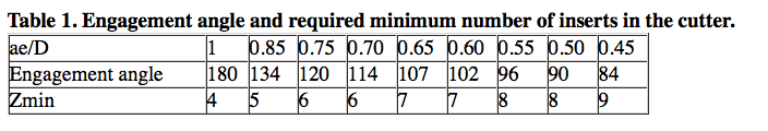
The formula for calculating the engagement angle (α) was described and explained in the July 2010 CTE article “New Mill.” The engagement angle depends on the radial WOC (ae) and the mill’s diameter (D). Table 1 shows the engagement angles and respective required minimum number of inserts (Zmin) in the facemill to ensure two inserts are engaged with the workpiece. The required minimum number of inserts is a guideline for selecting the appropriate facemill based on nomenclature in a toolmaker’s catalog.
Cutting Geometry
A facemill’s cutting geometry is usually one of the following:
• Double positive (positive axial rake and positive radial rake)
• Positive negative (positive axial and negative radial rake)
• Double negative (negative axial and negative radial rake)
The angular relations of the cutting edge greatly impact cutting efficiency. Axial rake controls chip flow, tangential force and cutting edge strength. Contemporary facemills have positive rake angles, typically from 5° to 20°. An increase in axial rake reduces tangential force and edge strength.
Radial rake has a major influence on chip evacuation and tool life. Positive radial rake angles typically range from 1° to 14°. Positive rake angles direct chips up and away from the workpiece. Negative radial rake angles, which strengthen cutting edges, typically range from -2° to -11°.
Facemills with positive-negative and double-positive geometries are applied for cutting carbon, alloy and stainless steels; ductile and malleable cast irons; titanium alloys; and high-temperature alloys. Facemills with double-positive geometries are mainly used for cutting aluminum alloys and some other nonferrous materials.
Lead angle (λ) is the angle between the side-cutting edge of the insert and the line parallel to the axis of rotation (Figure 2). This definition agrees with customary U.S. units of measure.
The angle between the side-cutting edge of the insert and line perpendicular to the axis of rotation agrees with the metric units of measure (Figure 3). This angle (γ) is called “cutting edge angle” or “approach angle.” Based on their definitions, lead and approach angles relate to each other as:
λ = 90° - γ (3)
γ = 90° - λ (4)
Facemills with a 0° lead angle and 90° approach angle produce chips that have a thickness equal to the feed per tooth. Facemills with a lead angle greater than 0° or an approach angle less than 90° produce chips thinner than the feed per tooth.
Lead angles can vary from 0° to 45°. Other lead angle values can be 15°, 20° and 30°, which are equivalent to approach angles of 75°, 70° and 60°, respectively. The most common lead or approach angle is 45°.

Figure 2. Lead angle is the angle between the side-cutting edge of the insert and the line parallel to the axis of rotation.

Figure 3. Approach angle is the angle between the side-cutting edge of the insert and line perpendicular to the axis of rotation.
These angles affect chip thickness (hm): at 0° lead angle (90° approach angle), the chip thickness equals feed per tooth (fz). At any other angle, chip thickness is defined by the formulas:
hm = fz cosλ (5)
hm = fz sinγ (6)
Adjustment to chip thickness is needed to increase the feed per tooth (fza) and keep the same productivity as when using a 0° (90°) lead (approach) angle:
fza = fz ÷ cosλ (7)
fza = fz ÷ sinγ (8)
Milling Parameters
Programmed milling parameters include axial DOC (ap), feed per tooth (fz), cutting speed (VC) and radial WOC (ae). Axial DOC depends on the indexable-insert geometries, carbide grades and workpiece hardness. When roughing, the axial DOC is about one-half of the height of the insert.
Feeds per tooth are established values based on the following values:
• 0.003 " to 0.006 " for light milling
• 0.006 " to 0.010 " for medium milling
• 0.010 " to 0.020 " for heavy-duty milling
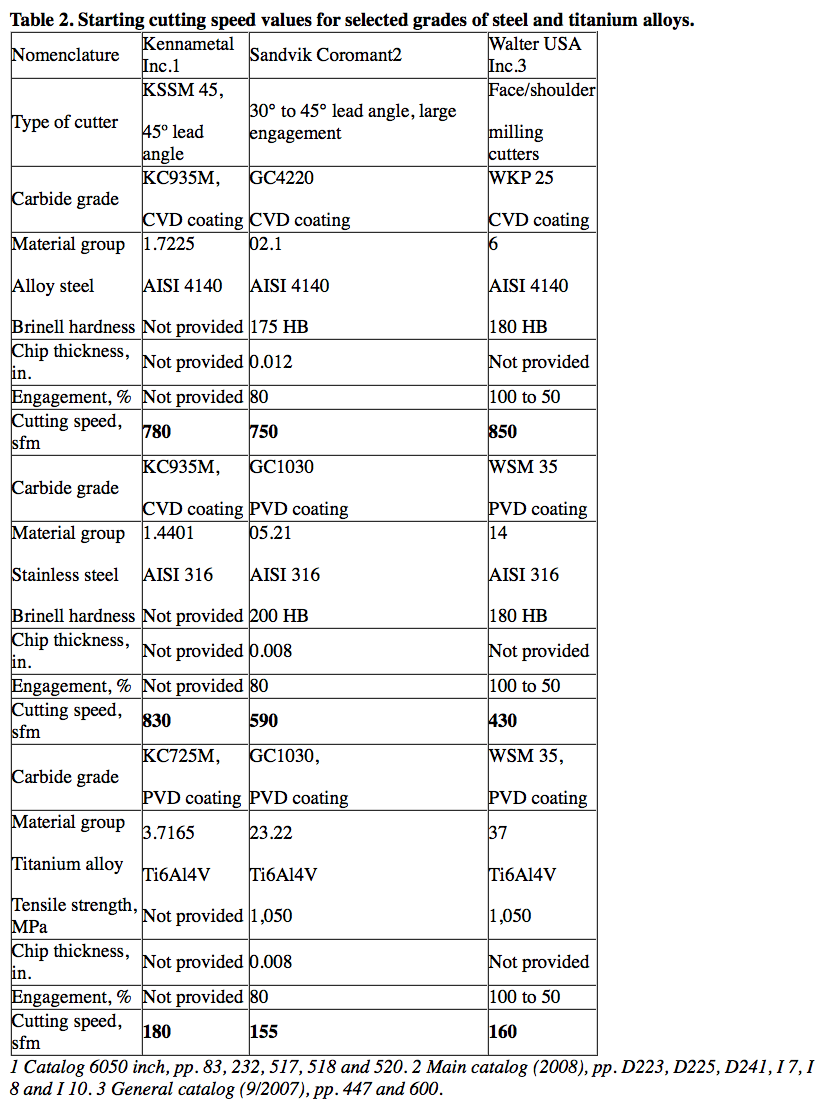
Cutting speeds vary greatly based on recommendations from cutting tool manufacturers (Table 2 on page 66). Cutting speed data is based on the type of work material, its hardness, cemented carbide grades, chip thickness and the ratio (ae ÷ Dc) of the radial WOC (ae) to the facemill diameter (D).
Enlarged view

Negative angle of entry
Courtesy of Kennametal
Figure 4. A negative angle of entry is recommended whenever possible because the insert contacts the workpiece at its strongest part, which is away from the cutting edge.
Selecting cutting speed is a challenge. There are no set criteria for choosing cutting speed because too many independent variables are involved in milling. If machine shops are not sure about the cutting speed, they should contact their cutting tool supplier for recommendations.
Selecting the radial WOC (ae) is also a challenge because it plays several important roles.
1. Along with axial DOC and feed rate, it affects metal-removal rate. An increase in the radial WOC increases the mrr.
2. The ratio of the radial WOC to the cutter’s diameter is a measure of the radial engagement of a cutter with a workpiece. Radial WOC defines the position of the cutter centerline: If ae is greater than D ÷ 2, the cutter centerline is located on the workpiece; when ae is less than D ÷ 2, the cutter centerline is not located on the workpiece.
3. The ratio of ae ÷ D determines the uniformity of chip thickness. When radial WOC is equal to the cutter’s diameter (ae ÷ D = 1, i.e. full engagement), the chip being formed starts at zero thickness at the point of entry. It increases to a maximum thickness at the centerline of the cutter, and thins to zero at the point of exit. This type of cut produces nonuniform chips, generates maximum friction at the cutting edges, and, as a result, cutting resistance increases. Full engagement should not be used unless absolutely necessary. Uniform and sufficiently thick chips are produced when the radial WOC is about 70 to 75 percent of the cutter’s diameter. This type of cut generates less friction at the cutting edges and decreases cutting resistance.
4. Radial WOC defines the cutter’s angle of entry into a workpiece, which can be negative or positive. If the cutter’s centerline is on the workpiece (ae is greater than D ÷ 2), the angle of entry is negative (Figure 4). A negative angle of entry is recommended whenever possible because the insert contacts the workpiece at its strongest part, which is away from the cutting edge. If the cutter’s centerline is not on the workpiece (ae is less than D ÷ 2), the angle of entry is positive (Figure 5). A positive angle of entry is not recommended because the insert contacts the workpiece with the cutting edge, which is the weakest part. That can result in insert chipping. If a positive angle of entry is necessary, then a more shock-resistant carbide grade and a cutting edge with a T-land or hone are recommended.
5. When the radial WOC is less than half the facemill’s diameter (ae is less than D ÷ 2), a feed rate adjustment (Fa) is necessary to maintain the same productivity (the same mrr) as when the radial WOC is higher than half the facemill diameter, i.e. (ae is greater than D ÷ 2). The following formula can be used for the adjustment:

Where fz is feed per tooth (in.), Z is the number of inserts in a cutter, n is the rotational speed of a cutter (rpm), D is cutter diameter (in.), ae is radial WOC (in.), and R is cutter radius (in.).
Milling Machines
Milling is performed in almost every type of machine that can rigidly hold and rotate a cutter while moving a workpiece toward the cutter or vise versa. Machines used for production milling should incorporate:
• Variable-speed motors
• Ballscrew or hydrostatic worm precision gears and bearings
• Hydrostatic liners
• NC or CNC
• Automatic drives
• Automatic toolchangers
Machines that drive cutters with horizontal and vertical spindles are widely used. Some special-purpose machines have horizontal, vertical and angular spindles that operate consecutively, simultaneously or both.
Enlarged view

Positive angle of entry
Courtesy of Kennametal
Figure 5. A positive angle of entry is not recommended because the insert contacts the workpiece with the cutting edge, which is the weakest part. That can result in the insert chipping. If a positive angle of entry is necessary, then a more shock-resistant carbide grade and a cutting edge with a T-land or hone are recommended.
[Note: Information in this section is adapted from Metals Handbook, Ninth Edition, Volume 16, Machining, ASM International, fourth printing, 1999.]
Regardless of the type of milling machine, the following specifications should be available to allow setup of the machine for maximum productivity.
• Spindle maximum rating, hp (kW)
• Spindle maximum torque, ft.-lbs. (N∙m)
• Spindle speed at maximum torque, rpm
• Spindle maximum speed, rpm
• Spindle (or main drive) efficiency factor, percent.
The following example shows how the three elements of an integrated face-milling system (workpiece hardness, facemill nomenclature with selected cutting parameters and milling machine specification) interact to produce the required power and torque values in comparison with those available from a given milling machine.
(The following technical information was adapted from Metals Handbook, Ninth Edition, Volume 16, Machining.)
1. Workpiece:
1030 steel plate, hardness 165 to 185 HB
Width, 12 "; length, 147 "
2. Facemill nomenclature:
Diameter, 16.0 "
Number of teeth, 32 (cemented carbide inserts)
Machining conditions:
Spindle speed, 72 rpm
WOC, 12.0 "
DOC, 0.125 "
Feed per tooth, 0.027 "
3. Machine tool specification:
Fixed-rail, bed-type milling machine
Vertical spindle maximum rating, 100 hp
Calculated data:
Cutting speed, 302 sfm
Feed rate, 62 ipm
mrr, 122 in.3/min.*
Power required at the cutter, 95 hp
* The mrr of 122 in.3/min. is incorrect. Based on the WOC, DOC and feed rate, the mrr = 12 × 0.125 × 62 = 93 in.3/min.
[Note: It is obvious that the calculation of the required power was performed by the conventional method based on the mrr and the average unit power. The conventional method was described by the author in “New Mill” (CTE, July 2010, p.46).]
Based on the previous information, the author performed the calculations using his new method described in the “New Mill” article. Contemporary metalcutting terminology is used.
1. Workpiece:
Medium-carbon steel, AISI 1030
Brinell hardness, 165 to 185 HB
The higher number of hardness (185 HB) is taken for calculating the ultimate tensile strength (σ) using the linear regression formula developed by the author.
σ = 471 × HB + 4,376 = 471 × 185 + 4,376 = 91,500 psi
2. Facemill:
Nomenclature is the same as shown previously.
Machining conditions:
Cutting speed, 302 sfm
Radial WOC, 12.0 "
Axial DOC, 0.125 "
Feed per tooth, 0.027 "
3. Machine tool:
Specification is the same as shown previously.
Calculated data:
Milling calculator developed by the author was used to perform conventional and advanced calculations (the calculated data is shown below).
Conventional calculations:
Spindle speed, 72 rpm
Feed rate, 62.3 ipm
mrr, 93.4 in.3/min.
Cutting time per pass, 2.36 min.
Advanced calculations
Number of teeth (inserts) in the cut, 11
Tangential cutting force with sharp cutting edges, 4,940 lbs.
Tangential cutting force with dull cutting edges, 6,420 lbs. [4,940 × 1.3 (1.3 is a tool wear factor, Cw)]
Torque at the cutter with sharp cutting edges, 3,290 ft.-lbs.
Torque at the cutter with dull cutting edges, 4,280 ft.-lbs. (3,290 × 1.3)
Power required at the cutter with sharp cutting edges, 45.2 hp
Power required at the cutter with dull cutting edges, 58.8 hp (45.2 × 1.3)
Power required at the main drive with sharp cutting edges, 56.5 hp (45.2 ÷ 0.8); estimated main drive efficiency factor, E = 0.8
Power required at the main drive with dull cutting edges, 73.5 hp (58.8 ÷ 0.8)
The new calculation method allows users to obtain data not available from the conventional calculation method. That data includes ultimate tensile strength vs. workpiece hardness, number of teeth (inserts) in the cut, tangential cutting force when the cutting edges are sharp or dull, and torque at the cutter when the cutting edges are sharp or dull. The power required for a milling operation shown in this example is less than 50 percent of that estimated by the conventional method. CTE
 About the Author: Edmund Isakov, Ph.D., is a consultant, writer and frequent contributor to CTE. He is the author of the books “Mechanical Properties of Work Materials” (Modern Machine Shop Publications, 2000), “Engineering Formulas for Metalcutting” (Industrial Press, 2004), “Cutting Data for Turning of Steel” (Industrial Press, 2009) and the software “Advanced Metalcutting Calculators” (Industrial Press, 2005). He can be e-mailed at [email protected] or reached at (561) 369-4063.
Related Glossary Terms
- Brinell hardness number ( HB)
Brinell hardness number ( HB)
Number related to the applied load (usually, 500 kgf and 3,000 kgf) and to the surface area of the permanent impression made by a 10mm ball indenter. The Brinell hardness number is a calculated value of the applied load (kgf) divided by the surface area of the indentation (mm2). Therefore, the unit of measure of a Brinell hardness number is kgf/mm2, but it is always omitted.
- Brinell hardness number ( HB)2
Brinell hardness number ( HB)
Number related to the applied load (usually, 500 kgf and 3,000 kgf) and to the surface area of the permanent impression made by a 10mm ball indenter. The Brinell hardness number is a calculated value of the applied load (kgf) divided by the surface area of the indentation (mm2). Therefore, the unit of measure of a Brinell hardness number is kgf/mm2, but it is always omitted.
- alloys
alloys
Substances having metallic properties and being composed of two or more chemical elements of which at least one is a metal.
- aluminum alloys
aluminum alloys
Aluminum containing specified quantities of alloying elements added to obtain the necessary mechanical and physical properties. Aluminum alloys are divided into two categories: wrought compositions and casting compositions. Some compositions may contain up to 10 alloying elements, but only one or two are the main alloying elements, such as copper, manganese, silicon, magnesium, zinc or tin.
- angle of entry
angle of entry
Determined by the position of the milling cutter’s centerline relative to the edge of the workpiece. Depending on the cutter diameter and the radial width of cut, the angle of entry can be negative or positive. A negative angle of entry occurs when the cutter’s centerline is located on the workpiece. Such an angle is recommended because the insert contacts the workpiece by its strong front rake, not by its weak cutting edge. To produce a negative angle of entry, the radial width of cut should exceed the cutter radius. A positive angle of entry occurs when the cutter’s centerline is not located on the workpiece. It happens when the radial width of cut is less than the cutter radius. A positive angle of entry should be avoided because the insert contacts the workpiece by its weakest part—the cutting edge.
- approach angle
approach angle
Angle between the insert’s side-cutting edge and the line perpendicular to the milling cutter’s axis of rotation. Approach angle, which is also known as cutting edge angle, is used with metric units of measurement. See lead angle.
- axial rake
axial rake
On angular tool flutes, the angle between the tooth face and the axial plane through the tool point.
- chatter
chatter
Condition of vibration involving the machine, workpiece and cutting tool. Once this condition arises, it is often self-sustaining until the problem is corrected. Chatter can be identified when lines or grooves appear at regular intervals in the workpiece. These lines or grooves are caused by the teeth of the cutter as they vibrate in and out of the workpiece and their spacing depends on the frequency of vibration.
- computer numerical control ( CNC)
computer numerical control ( CNC)
Microprocessor-based controller dedicated to a machine tool that permits the creation or modification of parts. Programmed numerical control activates the machine’s servos and spindle drives and controls the various machining operations. See DNC, direct numerical control; NC, numerical control.
- cutting force
cutting force
Engagement of a tool’s cutting edge with a workpiece generates a cutting force. Such a cutting force combines tangential, feed and radial forces, which can be measured by a dynamometer. Of the three cutting force components, tangential force is the greatest. Tangential force generates torque and accounts for more than 95 percent of the machining power. See dynamometer.
- cutting speed
cutting speed
Tangential velocity on the surface of the tool or workpiece at the cutting interface. The formula for cutting speed (sfm) is tool diameter 5 0.26 5 spindle speed (rpm). The formula for feed per tooth (fpt) is table feed (ipm)/number of flutes/spindle speed (rpm). The formula for spindle speed (rpm) is cutting speed (sfm) 5 3.82/tool diameter. The formula for table feed (ipm) is feed per tooth (ftp) 5 number of tool flutes 5 spindle speed (rpm).
- facemill
facemill
Milling cutter for cutting flat surfaces.
- facemilling
facemilling
Form of milling that produces a flat surface generally at right angles to the rotating axis of a cutter having teeth or inserts both on its periphery and on its end face.
- feed
feed
Rate of change of position of the tool as a whole, relative to the workpiece while cutting.
- gang cutting ( milling)
gang cutting ( milling)
Machining with several cutters mounted on a single arbor, generally for simultaneous cutting.
- hardness
hardness
Hardness is a measure of the resistance of a material to surface indentation or abrasion. There is no absolute scale for hardness. In order to express hardness quantitatively, each type of test has its own scale, which defines hardness. Indentation hardness obtained through static methods is measured by Brinell, Rockwell, Vickers and Knoop tests. Hardness without indentation is measured by a dynamic method, known as the Scleroscope test.
- inches per minute ( ipm)
inches per minute ( ipm)
Value that refers to how far the workpiece or cutter advances linearly in 1 minute, defined as: ipm = ipt 5 number of effective teeth 5 rpm. Also known as the table feed or machine feed.
- lead angle
lead angle
Angle between the side-cutting edge and the projected side of the tool shank or holder, which leads the cutting tool into the workpiece.
- metal-removal rate
metal-removal rate
Rate at which metal is removed from an unfinished part, measured in cubic inches or cubic centimeters per minute.
- metalcutting ( material cutting)
metalcutting ( material cutting)
Any machining process used to part metal or other material or give a workpiece a new configuration. Conventionally applies to machining operations in which a cutting tool mechanically removes material in the form of chips; applies to any process in which metal or material is removed to create new shapes. See metalforming.
- milling
milling
Machining operation in which metal or other material is removed by applying power to a rotating cutter. In vertical milling, the cutting tool is mounted vertically on the spindle. In horizontal milling, the cutting tool is mounted horizontally, either directly on the spindle or on an arbor. Horizontal milling is further broken down into conventional milling, where the cutter rotates opposite the direction of feed, or “up” into the workpiece; and climb milling, where the cutter rotates in the direction of feed, or “down” into the workpiece. Milling operations include plane or surface milling, endmilling, facemilling, angle milling, form milling and profiling.
- milling machine ( mill)
milling machine ( mill)
Runs endmills and arbor-mounted milling cutters. Features include a head with a spindle that drives the cutters; a column, knee and table that provide motion in the three Cartesian axes; and a base that supports the components and houses the cutting-fluid pump and reservoir. The work is mounted on the table and fed into the rotating cutter or endmill to accomplish the milling steps; vertical milling machines also feed endmills into the work by means of a spindle-mounted quill. Models range from small manual machines to big bed-type and duplex mills. All take one of three basic forms: vertical, horizontal or convertible horizontal/vertical. Vertical machines may be knee-type (the table is mounted on a knee that can be elevated) or bed-type (the table is securely supported and only moves horizontally). In general, horizontal machines are bigger and more powerful, while vertical machines are lighter but more versatile and easier to set up and operate.
- milling machine ( mill)2
milling machine ( mill)
Runs endmills and arbor-mounted milling cutters. Features include a head with a spindle that drives the cutters; a column, knee and table that provide motion in the three Cartesian axes; and a base that supports the components and houses the cutting-fluid pump and reservoir. The work is mounted on the table and fed into the rotating cutter or endmill to accomplish the milling steps; vertical milling machines also feed endmills into the work by means of a spindle-mounted quill. Models range from small manual machines to big bed-type and duplex mills. All take one of three basic forms: vertical, horizontal or convertible horizontal/vertical. Vertical machines may be knee-type (the table is mounted on a knee that can be elevated) or bed-type (the table is securely supported and only moves horizontally). In general, horizontal machines are bigger and more powerful, while vertical machines are lighter but more versatile and easier to set up and operate.
- numerical control ( NC)
numerical control ( NC)
Any controlled equipment that allows an operator to program its movement by entering a series of coded numbers and symbols. See CNC, computer numerical control; DNC, direct numerical control.
- parallel
parallel
Strip or block of precision-ground stock used to elevate a workpiece, while keeping it parallel to the worktable, to prevent cutter/table contact.
- radial rake
radial rake
Also known as the tool back rake, the angle between the tooth face and the radial plane through the tool point.
- rake
rake
Angle of inclination between the face of the cutting tool and the workpiece. If the face of the tool lies in a plane through the axis of the workpiece, the tool is said to have a neutral, or zero, rake. If the inclination of the tool face makes the cutting edge more acute than when the rake angle is zero, the rake is positive. If the inclination of the tool face makes the cutting edge less acute or more blunt than when the rake angle is zero, the rake is negative.
- tensile strength
tensile strength
In tensile testing, the ratio of maximum load to original cross-sectional area. Also called ultimate strength. Compare with yield strength.
- turning
turning
Workpiece is held in a chuck, mounted on a face plate or secured between centers and rotated while a cutting tool, normally a single-point tool, is fed into it along its periphery or across its end or face. Takes the form of straight turning (cutting along the periphery of the workpiece); taper turning (creating a taper); step turning (turning different-size diameters on the same work); chamfering (beveling an edge or shoulder); facing (cutting on an end); turning threads (usually external but can be internal); roughing (high-volume metal removal); and finishing (final light cuts). Performed on lathes, turning centers, chucking machines, automatic screw machines and similar machines.