Meeting micromachining's need for speed

Author Larry Adams
Published
May 13, 2020 - 10:30am

Microscale parts and features present many challenges when machining, not least of which are the high spindle speeds required to reach acceptable cutting speeds and cut rather than rub workpieces or break tools. A lot of shops have robust, accurate equipment that has served them well through the years but lacks adequate spindle speed.

Many machines are built for torque, not speed. A solution might be a specialized micromachine or a premium machine with a high-speed spindle, but a spindle speeder is another option.

Spindle speeders amplify speeds for many jobs that need small-diameter tools, often less than 6 mm (0.24"). Speeders multiply spindle speeds by several times while maintaining the torque of a machine.

“The biggest problem with (using) small tools is that the shop can’t run them fast enough,” said Steve Bryan, owner of Bryan Machine Service Inc., Huntington, Indiana. “Spindle speeders can take an older machine and increase that up to 15,000 to 40,000 rpm. The older machines have a new life.”

Spindle speeders are suitable for myriad shank types, including small tapers that are lightweight and precisely produced for balance and reduced total indicator runout.


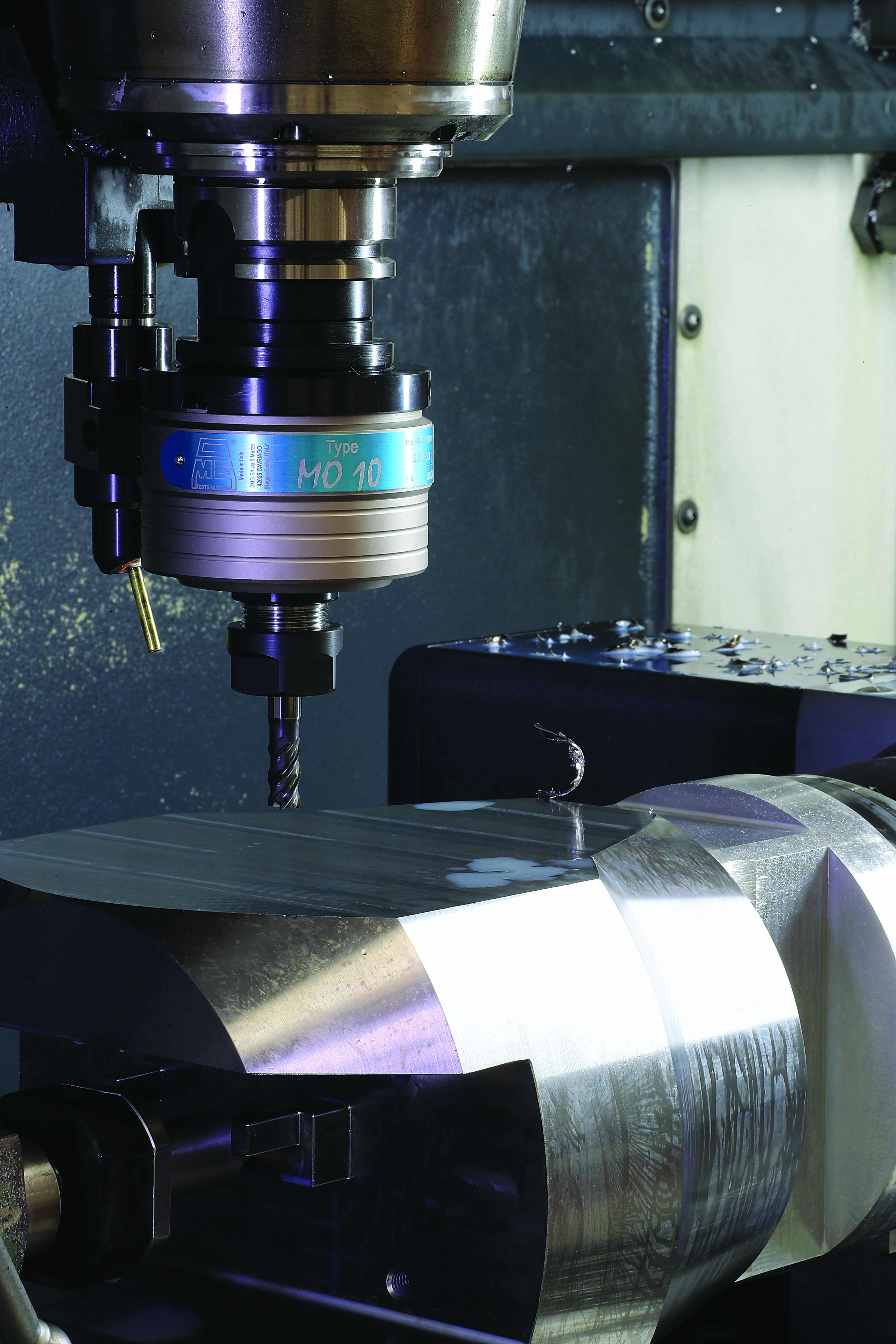
The MO spindle speeder for micromachining applications can increase spindle speeds to 35,000 rpm. Image courtesy of OMG North America

Because higher-end spindle speeders are compatible with automatic tool changers, it is easy to do multiple setups on one machine. For example, in addition to producing and selling its line of VRT spindle speeders, Bryan Machine Service operates a machine shop. Sitting amid a variety of higher-tech equipment are two 50-taper, 7,000-rpm machines. One job required machining runners on a large plate, as well as microfeatures.

“With the spindle speeder,” Bryan said, “we can put on a 1⁄8"- (3.18 mm) or a 1⁄16"-dia. (1.59 mm) tool on that great big machine and run it at 30,000 rpm.”

Need for Speed

Faster spindle speeds can help impart fine surface finishes and reduce burrs, chatter marks and other cosmetic blemishes. Carbide cutting tools also require higher spindle speeds for best results.

The trick is to run at the right surface feet per minute, which also can be expressed in surface meters per minute. Essentially, the faster a spindle turns or the larger the diameter of a tool is, the higher the sfm is based on the formula in which sfm equals (rpm times tool diameter) divided by 3.82. For instance, a 0.5"-dia. (12.7 mm) endmill running at 1,146 rpm achieves a cutting speed of 150 sfm (45.72 m/min.) while a 0.05" (1.27 mm) tool must run at 11,459 rpm to cut at 150 sfm, and a 0.005" (0.127 mm) tool needs an 114,592-rpm spindle speed to reach 150 sfm.

But those numbers are just the start. Different materials cut best at specific speeds, and each tool supplier suggests cutting speeds for its tools.

“When machining material like aluminum, the tool manufacturers might recommend a surface speed as high as 350 sfm (106.68 m/min.), and if you wanted to run a 1 mm (0.039") carbide drill, you would need 35,000 rpm to reach that surface speed recommendation,” said Mark Johnson, manager of OMG North America, Post Falls, Idaho.

The company offers the MO series of spindle speeders, including the MO10.HS for micromachining applications with a maximum output speed of 35,000 rpm.

Meeting Challenges

If a machine can’t deliver the spindle speed to meet the required cutting speed, mechanical or cosmetic issues may occur, such as chatter marks.

Even something as common as clogged flutes is problematic, said John Young, president of Eltool Corp., a Mansfield, Ohio-based supplier of spindle speeders, right-angle spindle heads and live tooling.


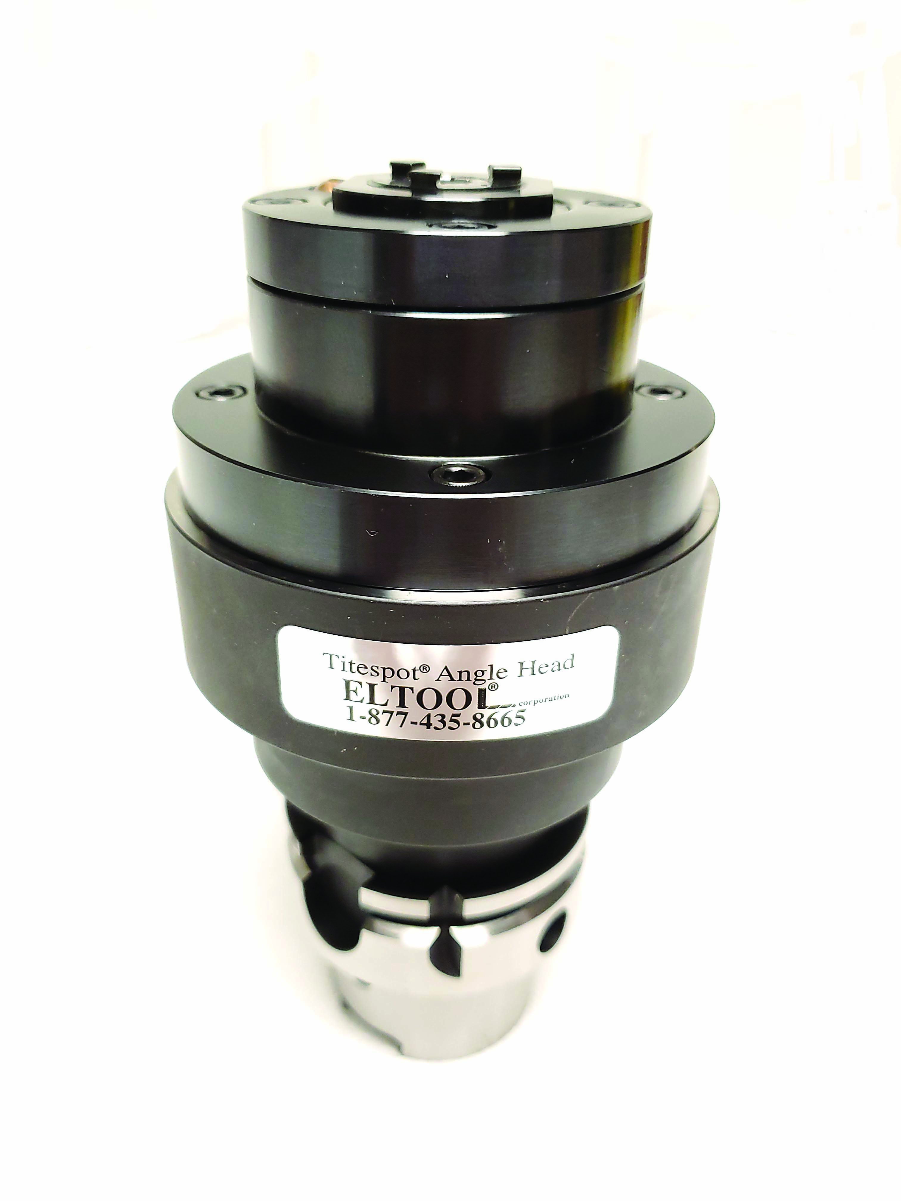
A coolant-driven spindle speeder is displayed. Image courtesy of Eltool

“People who run aluminum at lower rpm just weld the whole chunk of aluminum right onto the cutter,” he said. “That is why it is so critical to get the surface feed up, so the tool doesn’t stay in the material long enough to stick to the tool.”

High speeds are key but challenging to achieve. A machine running at or near its maximum rpm can have balance and runout issues, generate friction-caused thermal expansion that burns out bearings and gears and potentially distort tools during operation.

Spindle speeder suppliers, however, have developed methods to overcome many of these problems. For example, when Bryan made his spindle speeder turbine system, one of his must-haves was a short distance between a spindle and workpiece.

“The further you get away from the machine spindle,” he said, “the more vibration you get.”

Eltool’s speeders are powered by high-pressure coolant as opposed to running a machine tool with a spinning spindle that has additional components installed, such as a torque arm.

“In our case,” Young said, “we don’t need a torque arm. We don’t need the spindle on. We just need the coolant on to run through our ball piston motor, creating very high rpm with very little reciprocating weight for very smooth, vibration-free machining.”

Having good concentricity is important when running at high spindle speeds, Johnson said.

“Anytime you add another element between the cutting tool and the machine spindle, there’s the possibility to have a greater amount of runout,” he said. “The spindle speeders that we produce have a high accuracy between the machine spindle taper and the output spindle of the speeder. The maximum runout allowance is just 1 µm, or 0.000039". Often the resulting runout is significantly less.”

Speeder Types

Spindle speeders and high-speed attachments come in various types and styles, as well as power sources. Mechanical speeders are driven by a machine spindle and increase its speed as a fixed ratio. Electric, air turbine and coolant-driven attachments are powered by their respective sources of energy.

The mechanical type utilizes a planetary gearbox to drive the speeder and convert every spindle rotation into a higher speed. Electric models typically employ 350W, DC brushless motors to generate up to 80,000 rpm. Other kinds use compressed air or high-pressure coolant to drive a spindle. They all have benefits and best uses.

Mechanical spindle speeders include those made by OMG North America.


VRT spindle speeders have a built-in regulator that adjusts pressure to provide the right amount of power. Image courtesy of Bryan Machine Service

These tried-and-true devices are built with high-quality bearings and gears, so they have a “very positive drive-through gearing and a very rugged construction,” Johnson said.

The highest-speed models feature two planetary gears with ratios of 1-8 for high transmission and high power ratings. The speeders are available with shanks for all machine spindles and have the option of through-tool coolant to be supplied through a machine spindle. A spindle is supported by a set of pre-loaded ball bearings with oblique contact that ensure strength and rotation precision of less than 0.01 mm (0.0004").

Bryan Machine Service’s VRT high-speed spindles have variable-speed adjustment and utilize air turbines, which do the actual turning instead of the machine spindle. The spindles feature an adjustable built-in regulator to maintain spindle speed as the cutting load varies.

“As the cut gets heavier,” Bryan said, “then it supplies itself with more air to adjust to the load.”

Operators adjust spring tension internally on the regulator via a button on the side of the spindle.

The unit also features an autocoupler that originally was designed for a Haas vertical machining center. The coupler is adaptable to most CNC machines, including lathes and grinders. When not in use, it is closed on each side to seal it from debris. An air wash feature blows away coolant before it can enter the spindle during the coupling.

“Any tool-changeable spindle gets a slight bit of coolant in it every time it couples, even if it is one drop,” Bryan said. “After thousands of cycles, it gets to be a problem eventually. This helps solve that problem.”

Eltool’s Titespot spindle speeders are powered by a positive displacement ball piston motor. Coupled to a high-pressure coolant system, this results in machining center spindle speeds of as much as 45,000 rpm.

Titespot speeders, which are available in common taper sizes, operate at 13.8 to 137.9 bar (200 to 2,000 psi) depending on the load. The standard speeder delivers 900 rpm per 3.8 liters (1 gal.) of coolant flow. With a 37.9-lpm (10-gpm) coolant delivery system, this equates to 9,000 rpm. But with the addition of a modular 1-5 planetary gearbox, spindle speed increases to 4,500 rpm per 3.8 liters of coolant flow. So the same 37.9-lpm system now delivers 45,000 rpm.

“The power has not changed,” Young said. “We just generated more speed by shifting into fourth gear.”

The speeders also can be adapted to lathes and are available in-line or as right-angle heads.    


Related Glossary Terms

  • chatter

    chatter

    Condition of vibration involving the machine, workpiece and cutting tool. Once this condition arises, it is often self-sustaining until the problem is corrected. Chatter can be identified when lines or grooves appear at regular intervals in the workpiece. These lines or grooves are caused by the teeth of the cutter as they vibrate in and out of the workpiece and their spacing depends on the frequency of vibration.

  • computer numerical control ( CNC)

    computer numerical control ( CNC)

    Microprocessor-based controller dedicated to a machine tool that permits the creation or modification of parts. Programmed numerical control activates the machine’s servos and spindle drives and controls the various machining operations. See DNC, direct numerical control; NC, numerical control.

  • coolant

    coolant

    Fluid that reduces temperature buildup at the tool/workpiece interface during machining. Normally takes the form of a liquid such as soluble or chemical mixtures (semisynthetic, synthetic) but can be pressurized air or other gas. Because of water’s ability to absorb great quantities of heat, it is widely used as a coolant and vehicle for various cutting compounds, with the water-to-compound ratio varying with the machining task. See cutting fluid; semisynthetic cutting fluid; soluble-oil cutting fluid; synthetic cutting fluid.

  • cutting speed

    cutting speed

    Tangential velocity on the surface of the tool or workpiece at the cutting interface. The formula for cutting speed (sfm) is tool diameter 5 0.26 5 spindle speed (rpm). The formula for feed per tooth (fpt) is table feed (ipm)/number of flutes/spindle speed (rpm). The formula for spindle speed (rpm) is cutting speed (sfm) 5 3.82/tool diameter. The formula for table feed (ipm) is feed per tooth (ftp) 5 number of tool flutes 5 spindle speed (rpm).

  • endmill

    endmill

    Milling cutter held by its shank that cuts on its periphery and, if so configured, on its free end. Takes a variety of shapes (single- and double-end, roughing, ballnose and cup-end) and sizes (stub, medium, long and extra-long). Also comes with differing numbers of flutes.

  • feed

    feed

    Rate of change of position of the tool as a whole, relative to the workpiece while cutting.

  • flutes

    flutes

    Grooves and spaces in the body of a tool that permit chip removal from, and cutting-fluid application to, the point of cut.

  • machining center

    machining center

    CNC machine tool capable of drilling, reaming, tapping, milling and boring. Normally comes with an automatic toolchanger. See automatic toolchanger.

  • shank

    shank

    Main body of a tool; the portion of a drill or similar end-held tool that fits into a collet, chuck or similar mounting device.

  • total indicator runout ( TIR)

    total indicator runout ( TIR)

    Combined variations of all dimensions of a workpiece, measured with an indicator, determined by rotating the part 360°.

  • turning

    turning

    Workpiece is held in a chuck, mounted on a face plate or secured between centers and rotated while a cutting tool, normally a single-point tool, is fed into it along its periphery or across its end or face. Takes the form of straight turning (cutting along the periphery of the workpiece); taper turning (creating a taper); step turning (turning different-size diameters on the same work); chamfering (beveling an edge or shoulder); facing (cutting on an end); turning threads (usually external but can be internal); roughing (high-volume metal removal); and finishing (final light cuts). Performed on lathes, turning centers, chucking machines, automatic screw machines and similar machines.

Contributors

Bryan Machine Service Inc.
260-356-5530
www.bryanmachine.com

Eltool Corp.
877-435-8665
www.eltool.com

OMG North America
866-440-8519
www.omgamerica.com