Efficient, productive machining involves many factors. Programmers, engineers and machinists need to master multiple important areas. Becoming adept at the use of key calculations is a critical matter.
Students, apprentices and trainees receive considerable instruction on gauges, machine alignments and operation of machine tools but often get insufficient education about shop math. Smartphones, computers, CAM software and conversational controls almost have eliminated the requirement for students to learn the subject. Many people believe that technological advances minimize the obligation of craftspeople to understand and use shop math, as evidenced by the marketing of software and controls that generate information that once was calculated by machinists and toolmakers.
Given the power of today’s digital tools, reducing the instructional time spent on shop math is not warranted. There are calculations and geometric concepts that everyone associated with machining should master.
Speed Equation
Calculating the proper cutting speed is vital whether using a million-dollar vertical machining center or 50-year-old knee mill. When milling, the cutting speed is a function of rpm and tool diameter. Learning to express the cutting speed in terms of rpm or sfm enhances technical communication by giving common terminology to everyone. Being able to work backward from rpm to sfm allows a person to propagate efficient cutting parameters across a range of tool diameters. Using rpm to define the cutting speed of a milling tool is the same as using rpm to define the speed of a car—it has no meaning by itself.

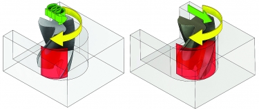
Understanding calculations associated with cutting speeds, feed rates and radial chip thinning enhances the use of advanced milling techniques, such as trochoidal milling. Toolpaths programmed with Mastercam’s Dynamic Machining suite produce radial chip thinning (left), whereas a traditional toolpath (right) doesn’t enable the productivity-enhancing benefits of radial chip thinning.
Once the cutting speed is established, the feed rate—the speed at which the tool traverses the workpiece—must be calculated. The most basic such calculation is: feed rate = rpm × the number of cutting teeth × the desired chip load, where the feed is expressed in ipm or mm/min. This is the “money” calculation because the feed rate is tied directly to the cycle time. A change in the feed usually is accompanied by a change in the cycle time, and feeding higher is almost always better for the bottom line.
Get Speeds and Feeds instantly based on dozens of parameters
Engineers and machinists should have a good understanding of chip thinning calculations and keep a reference source or calculator handy. As the DOC decreases for milling tools, there is a point at which the feed rate must increase to maintain the desired chip thickness. Chip thinning boosts the money calculation, so learning to manage chip thickness is a game changer.
A good example is work I did at a previous employer where a team of engineers significantly improved milling efficiency by using speed and feed calculations to determine the most effective cutting parameters. We had applied a 3/4"-dia. dovetail-style tool with four flutes and had horrible tool life as a result of the cutting speed being too high for the material. Reducing the cutting speed was not an option because that would have necessitated reducing the feed rate, hurting cycle time.

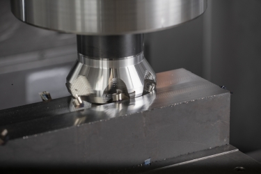
Shops with low-horsepower machines can enhance their facemilling operations with the Double Quattromill 14 facemilling cutter from Seco Tools LLC. Image courtesy of Seco Tools
The solution was to manufacture a custom 5/8"-dia. tool. We were able to increase the spindle speed while maintaining the optimal cutting speed, or sfm, which increased the feed rate. (Remember that the feed rate equals rpm times the number of cutting teeth times the desired chip load.) We also added four cutting edges, taking the total from four to eight, thereby doubling the feed rate while maintaining the proper chip load. Cycle times were slashed by two-thirds, and tool life tripled.
Coordinate System
Everyone operating a machining center should be taught to graph using the Cartesian coordinate system, the foundation of digital manufacturing. Anyone operating a machining center, coordinate measuring machine or similar device learns to maneuver through the X, Y, Z, A and B values needed to use the machine, but it can be a difficult, costly journey.
When people don’t understand the coordinate system, machine setup can be inefficient and making adjustments based on measurements, such as CMM data, can negatively impact quality. Becoming proficient with the Cartesian system on paper before moving to a machine tool improves efficiency and lowers the cost of quality.
Basic trigonometry is a must for anyone operating or programming a machining center. Bolt circle coordinates; true position data; I, J and K values for CNC programming; and countless other pieces of necessary machining information rely on trig calculations. Some would argue that CAD, CAM and other manufacturing software minimize the need for machinists to master basic trig. However, first mastering the concepts on paper increases the power of the digital tools and creates efficiency in the CAD/CAM environment.
We no longer are heading toward a digital machining environment. We already are immersed, and the most significant advances in manufacturing will be driven by digital technology. Elements like complete digital simulation, additive manufacturing and voice-controlled human-machine interfaces have moved beyond concepts. These are fully developed technologies, and their use in machining is expanding rapidly. Successful machining necessitates mastery of key calculations.
Related Glossary Terms
- computer numerical control ( CNC)
computer numerical control ( CNC)
Microprocessor-based controller dedicated to a machine tool that permits the creation or modification of parts. Programmed numerical control activates the machine’s servos and spindle drives and controls the various machining operations. See DNC, direct numerical control; NC, numerical control.
- computer-aided design ( CAD)
computer-aided design ( CAD)
Product-design functions performed with the help of computers and special software.
- computer-aided manufacturing ( CAM)
computer-aided manufacturing ( CAM)
Use of computers to control machining and manufacturing processes.
- cutting speed
cutting speed
Tangential velocity on the surface of the tool or workpiece at the cutting interface. The formula for cutting speed (sfm) is tool diameter 5 0.26 5 spindle speed (rpm). The formula for feed per tooth (fpt) is table feed (ipm)/number of flutes/spindle speed (rpm). The formula for spindle speed (rpm) is cutting speed (sfm) 5 3.82/tool diameter. The formula for table feed (ipm) is feed per tooth (ftp) 5 number of tool flutes 5 spindle speed (rpm).
- facemilling
facemilling
Form of milling that produces a flat surface generally at right angles to the rotating axis of a cutter having teeth or inserts both on its periphery and on its end face.
- feed
feed
Rate of change of position of the tool as a whole, relative to the workpiece while cutting.
- flutes
flutes
Grooves and spaces in the body of a tool that permit chip removal from, and cutting-fluid application to, the point of cut.
- gang cutting ( milling)
gang cutting ( milling)
Machining with several cutters mounted on a single arbor, generally for simultaneous cutting.
- inches per minute ( ipm)
inches per minute ( ipm)
Value that refers to how far the workpiece or cutter advances linearly in 1 minute, defined as: ipm = ipt 5 number of effective teeth 5 rpm. Also known as the table feed or machine feed.
- machining center
machining center
CNC machine tool capable of drilling, reaming, tapping, milling and boring. Normally comes with an automatic toolchanger. See automatic toolchanger.
- milling
milling
Machining operation in which metal or other material is removed by applying power to a rotating cutter. In vertical milling, the cutting tool is mounted vertically on the spindle. In horizontal milling, the cutting tool is mounted horizontally, either directly on the spindle or on an arbor. Horizontal milling is further broken down into conventional milling, where the cutter rotates opposite the direction of feed, or “up” into the workpiece; and climb milling, where the cutter rotates in the direction of feed, or “down” into the workpiece. Milling operations include plane or surface milling, endmilling, facemilling, angle milling, form milling and profiling.
- milling machine ( mill)
milling machine ( mill)
Runs endmills and arbor-mounted milling cutters. Features include a head with a spindle that drives the cutters; a column, knee and table that provide motion in the three Cartesian axes; and a base that supports the components and houses the cutting-fluid pump and reservoir. The work is mounted on the table and fed into the rotating cutter or endmill to accomplish the milling steps; vertical milling machines also feed endmills into the work by means of a spindle-mounted quill. Models range from small manual machines to big bed-type and duplex mills. All take one of three basic forms: vertical, horizontal or convertible horizontal/vertical. Vertical machines may be knee-type (the table is mounted on a knee that can be elevated) or bed-type (the table is securely supported and only moves horizontally). In general, horizontal machines are bigger and more powerful, while vertical machines are lighter but more versatile and easier to set up and operate.
- toolpath( cutter path)
toolpath( cutter path)
2-D or 3-D path generated by program code or a CAM system and followed by tool when machining a part.


