Making the most of tired CNC machining centers

Author Kip Hanson
Published
April 05, 2018 - 11:30am

You’ve probably heard the news: Milling has gone high performance. You’ve read the magazine articles about trochoidal milling, watched endless YouTube videos about high-feed and high-speed machining techniques and chatted with your cutting tools salesperson about plunge milling. Unfortunately, the newest machining centers at your shop were installed when Bill Clinton was president, and the oldest one still uses paper tape. 

So what difference do these and other high-tech milling strategies make to you?


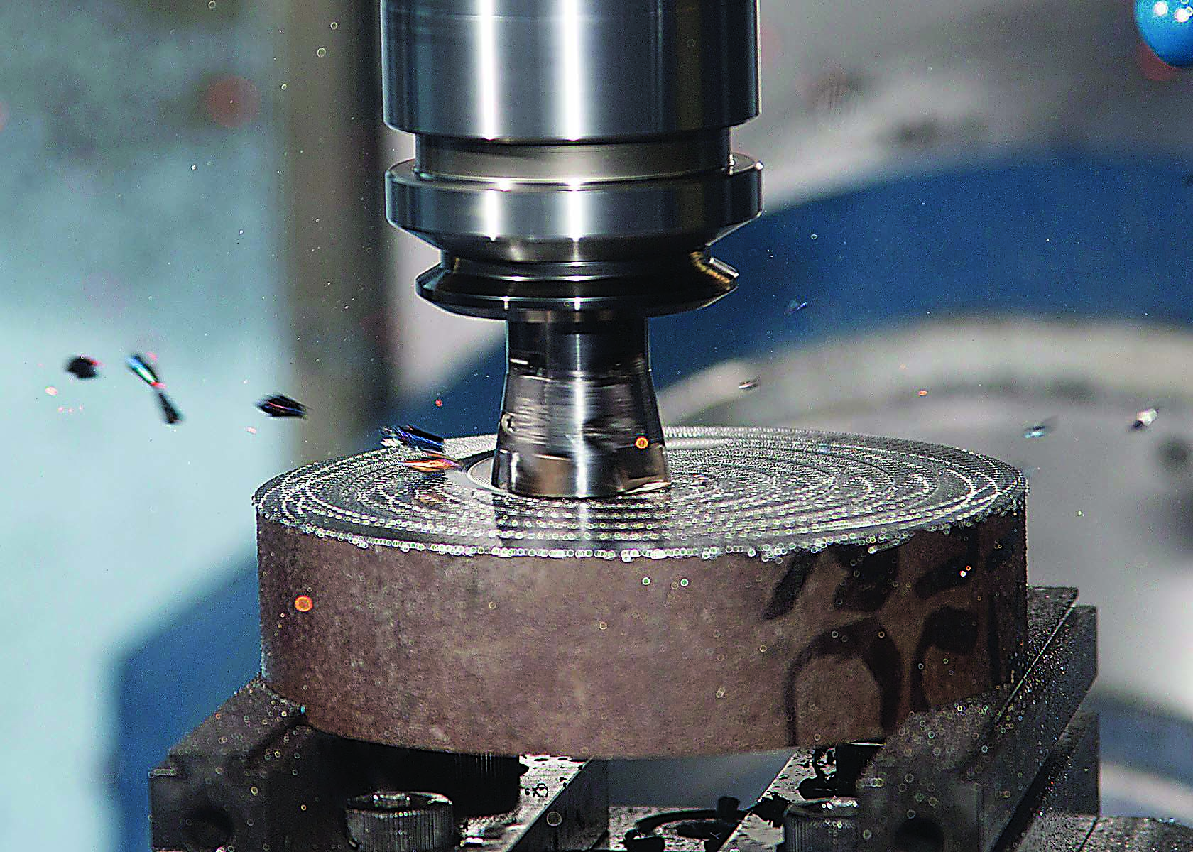
Image courtesy of Greenleaf.


Wouldn’t it be cool, though, to toss out those HSS corncob roughers with their 5-ipm (127mm/min.) feed rates and leverage some of these more productive milling methods? 

According to Tomas Roman, sales and applications manager for GWS Tool Group, Tavares, Fla., nothing is stopping you

Bye-Bye Corncobs

“We get calls every day from shops that either can’t afford or aren’t yet ready to buy a new machining center but still want to get better performance out of their existing equipment,” he said. “Most of the time, it’s just a matter of adjusting a high-performance milling strategy to match the capabilities of your machine tool.”

One example comes from an aluminum shop in the Dakotas that Roman worked with. A vintage machining center could barely rapid-traverse at the feed rates specified by the CAM system’s trochoidal toolpaths, let alone interpolate at those values. Another example is a power generation company machining titanium. The company’s older equipment was unable to meet a tool’s recommended speeds and feeds.

Despite the apples-and-oranges difference between machining aluminum and titanium, the answer in each case was to increase step-over amounts and reduce feed rates, even though the shop’s CAM software didn’t agree.


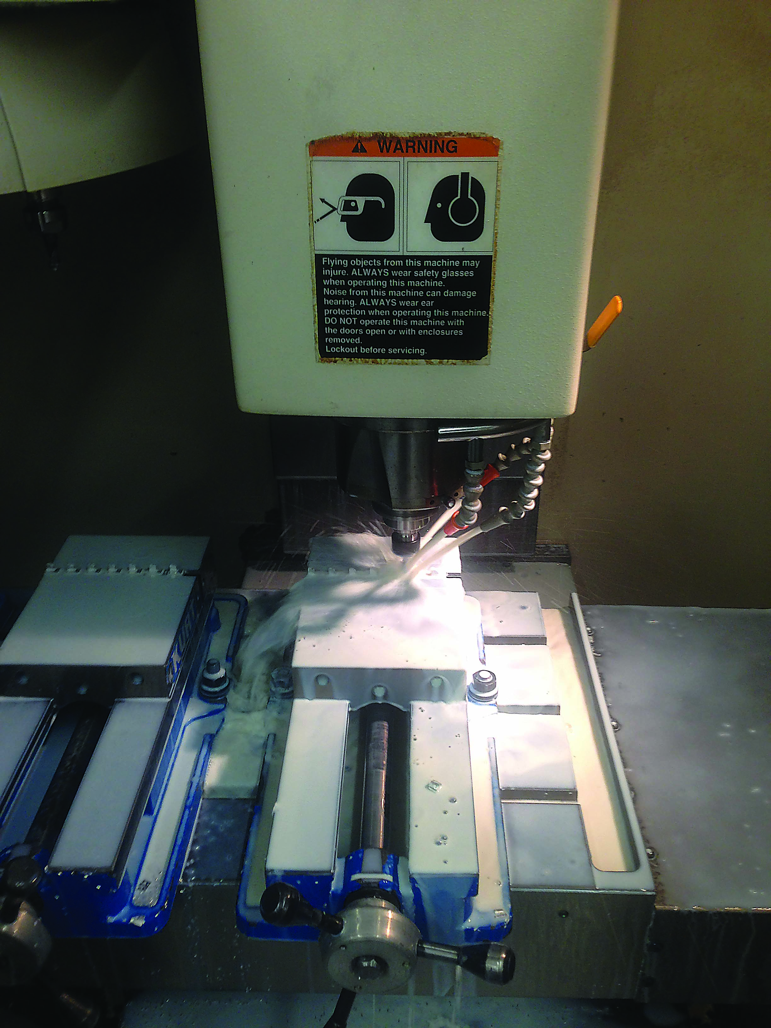
Unless special plumbing is installed, some carousel-style toolchangers can limit cutting fluids to the right side of the spindle, inhibiting chip flow. Image courtesy of GWS Tool Group.


“You can program any job at 500 ipm, but a lot of times the machine can’t accelerate and decelerate that quickly, something that’s true even on some newer equipment,” Roman said. “One indicator that this problem is occurring is when the actual machining cycle takes longer than what the programming software says it should. But by taking a more aggressive step-over and easing back on the feed, we were able to actually increase metal-removal rates compared to the original toolpaths.”

However, the less-than-optimal cutting conditions generated greater heat, which caused premature tool wear. The toolmaker countered by adjusting the tool geometry to make the endmills “a little bit beefier.” This meant tweaking the relief and rake angles, changing the edge prep to match the application and switching to a more heat-resistant coating.

According to Roman, this beefed-up approach is effective in many “old machine” situations, whether or not a newfangled toolpath is used. That’s because the backlash and lack of rigidity common with older CNCs require a cutting tool able to take abuse without complaint.

“Often with poor machining conditions,” Roman said, “heat’s going to be an issue. Aside from that, tool performance comes down to a delicate balance of aggressiveness and strength, while at the same time applying a carbide grade that’s stout enough for less-than-optimal cutting conditions.”

Happy With High Feed

One milling strategy that works especially well on older machines is high-feed milling. Most often, a special resembling a flattened ballnose endmill is applied with a shallow Z-axis, or axial, DOC, relatively heavy radial engagement (upward of 50 percent) and high feed rates, all of which tend to thin the chip while directing cutting forces into the spindle. Roman said one customer was able to replace seven separate tools with a pair of high-feed milling cutters, reducing cycle time and tool costs alike.

Vic Dodd, rotating-product manager for Tungaloy America Inc., Arlington Heights, Ill., saw similar results from his own days in the shop. “I once had a couple of 1997 Bridgeports that I used for mold work and had great results with high-feed tools,” he said, adding that with older equipment like that, the spindle isn’t strong and the servomotors are weaker than those found on newer machines. “The programmers need to understand those limitations if they’re to utilize what’s available.”


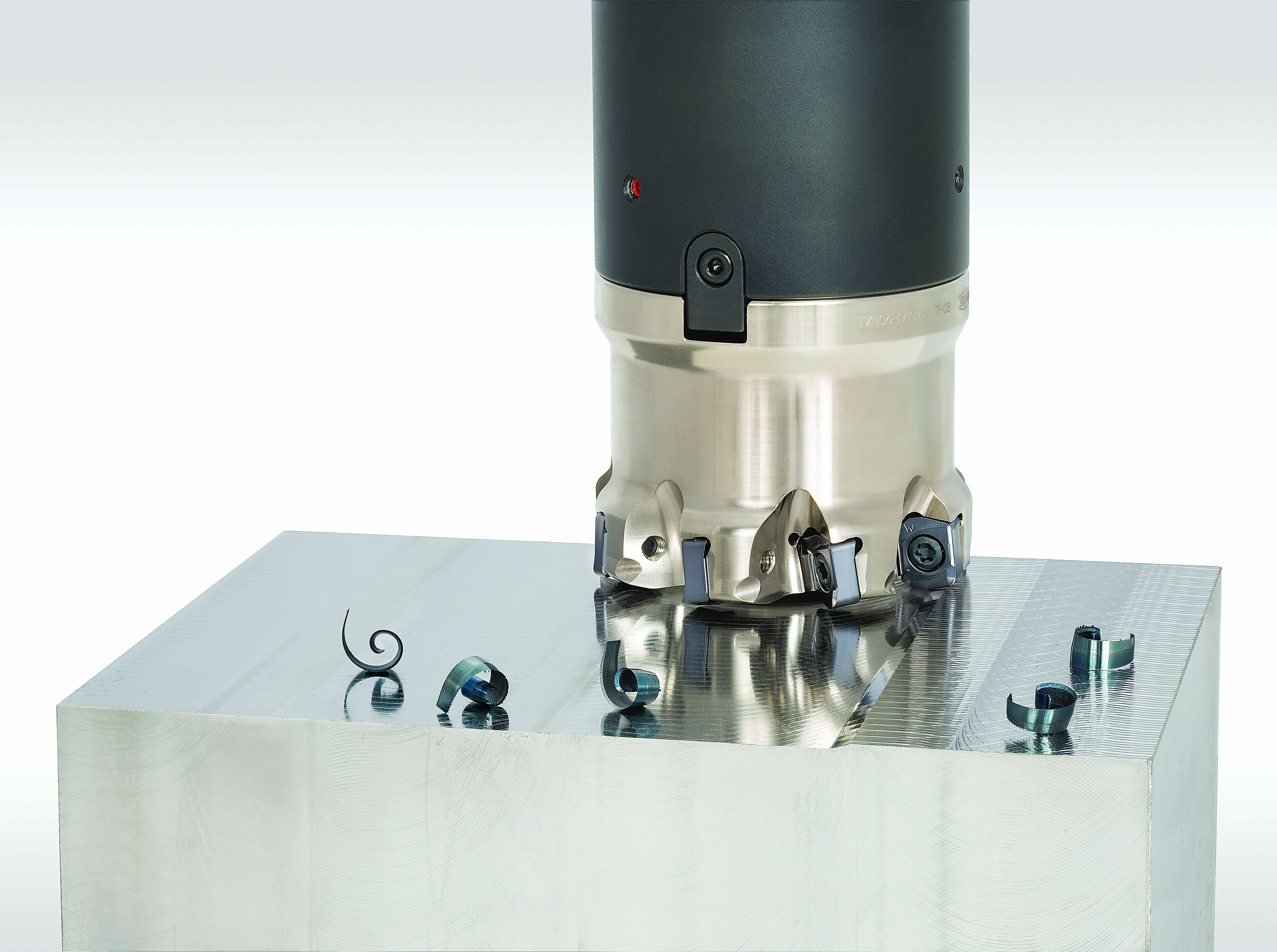
Indexable high-feed milling cutters are an effective machining method for old and new machines alike. Image courtesy of Tungaloy America.


Another limitation that many might recognize is coolant flow. With many older machining centers, Dodd explained, the horizontal, carousel-style toolchanger sits on the left side, a configuration that places the coolant lines on the right side of the spindle. “The problem here is that when you’re climb milling on the back of the part, the coolant is forcing the chips back into the cutter. That causes nothing but problems.”

Blast Away

There are two ways around this obstacle: Adjust the toolpath accordingly or turn off the coolant and apply an air blast. According to Dodd, the latter should be used by anyone cutting carbon steel, most tool steel and even some stainless steel. “Everybody wants to stick coolant on everything. It’s not really an advantage anymore in today’s modern machining. About the only time it is needed is when you’re drilling and tapping.”

That observation holds true for old and new machines alike. The only difference is that many newer machines are plumbed for through-spindle air or have an external air blast already wired in. 

Dodd offered another recommendation that has little to do with machine age: Replace toolholders regularly. “I see so many shops that use worn-out toolholders, not realizing that they’re not only hurting productivity, they’re damaging the machine spindle as well.”

Dodd said the same can be said for the Belleville washers and the clamping fingers inside the tool-change mechanism. “People keep running them long after they’ve worn out. Eventually, something breaks and they end up causing a lot of damage.”

The best way to avoid this situation is with proper machine maintenance, a practice that can keep even a
decades-old machine productive. In the meantime, Dodd recommends replacing toolholders and retention knobs at the first sign of wear.

New Chuck, Old Machine

Dodd also suggested tossing out the side-lock endmill mentality in favor of high-performance milling chucks, hydraulic holders and shrink-fit holders, even when used on machines built before any of those toolholding technologies were developed. 


A high-feed milling strategy is used to machine a 4140 alloy steel mold base on a legacy horizontal boring mill. Image courtesy of Tungaloy America.


“People consistently fail to realize how much more performance they’ll get from their machine tools—regardless of age—when they invest in high-quality tooling,” Dodd said.

Jan Andersson, global director of marketing for Greenleaf Corp., Saegertown, Pa., said success with tired machine tools—or any equipment, for that matter—is about understanding a machine’s limitations. “If you look at the industry in general, cutting tool recommendations are designed for average conditions on newer machines,” he said. “The problem is that, as machines get older, you begin to lose stability and accuracy.”

Andersson added that, at the same time, new machines with faster spindles and higher feed capabilities than vintage ones are being made, widening the gap. “This means that shops must adjust their machining strategies to match the machine tool, not just the application, and suppliers must support them in this effort.”

Embracing the Old-Timers

Shops should not avoid modern cutting tools or programming techniques. Instead, they should learn how to make the new and the old coexist. As painful as it may seem, unique CNC programs that respect a machine’s advanced age must be generated, resulting in multiple versions for jobs that bounce around a shop. This approach requires moderate cutting parameters that compensate for any specific infirmities, as well as cutting tools able to withstand greater heat and shock and less-than-ideal machining conditions.

As with the others interviewed for this story, Andersson said it’s important to stay current on machining technology, even if you can’t stay current on machine tools. “For example, people with older machines often discount ceramic as a cutting tool material because they don’t have the high spindle speeds needed to reach the correct operating parameters.” 

New materials have been developed that accommodate a much broader speed range and provide far greater performance than carbide. “That’s just one example where the industry has recognized that not every shop has new equipment and has taken steps to meet that need,” Andersson said. “It opens up a lot of opportunities for those with older, less-capable machine tools.”

Related Glossary Terms

  • backlash

    backlash

    Reaction in dynamic motion systems where potential energy that was created while the object was in motion is released when the object stops. Release of this potential energy or inertia causes the device to quickly snap backward relative to the last direction of motion. Backlash can cause a system’s final resting position to be different from what was intended and from where the control system intended to stop the device.

  • boring

    boring

    Enlarging a hole that already has been drilled or cored. Generally, it is an operation of truing the previously drilled hole with a single-point, lathe-type tool. Boring is essentially internal turning, in that usually a single-point cutting tool forms the internal shape. Some tools are available with two cutting edges to balance cutting forces.

  • centers

    centers

    Cone-shaped pins that support a workpiece by one or two ends during machining. The centers fit into holes drilled in the workpiece ends. Centers that turn with the workpiece are called “live” centers; those that do not are called “dead” centers.

  • chuck

    chuck

    Workholding device that affixes to a mill, lathe or drill-press spindle. It holds a tool or workpiece by one end, allowing it to be rotated. May also be fitted to the machine table to hold a workpiece. Two or more adjustable jaws actually hold the tool or part. May be actuated manually, pneumatically, hydraulically or electrically. See collet.

  • climb milling ( down milling)

    climb milling ( down milling)

    Rotation of a milling tool in the same direction as the feed at the point of contact. Chips are cut to maximum thickness at the initial engagement of the cutter’s teeth with the workpiece and decrease in thickness at the end of engagement. See conventional milling.

  • computer numerical control ( CNC)

    computer numerical control ( CNC)

    Microprocessor-based controller dedicated to a machine tool that permits the creation or modification of parts. Programmed numerical control activates the machine’s servos and spindle drives and controls the various machining operations. See DNC, direct numerical control; NC, numerical control.

  • computer-aided manufacturing ( CAM)

    computer-aided manufacturing ( CAM)

    Use of computers to control machining and manufacturing processes.

  • coolant

    coolant

    Fluid that reduces temperature buildup at the tool/workpiece interface during machining. Normally takes the form of a liquid such as soluble or chemical mixtures (semisynthetic, synthetic) but can be pressurized air or other gas. Because of water’s ability to absorb great quantities of heat, it is widely used as a coolant and vehicle for various cutting compounds, with the water-to-compound ratio varying with the machining task. See cutting fluid; semisynthetic cutting fluid; soluble-oil cutting fluid; synthetic cutting fluid.

  • endmill

    endmill

    Milling cutter held by its shank that cuts on its periphery and, if so configured, on its free end. Takes a variety of shapes (single- and double-end, roughing, ballnose and cup-end) and sizes (stub, medium, long and extra-long). Also comes with differing numbers of flutes.

  • feed

    feed

    Rate of change of position of the tool as a whole, relative to the workpiece while cutting.

  • gang cutting ( milling)

    gang cutting ( milling)

    Machining with several cutters mounted on a single arbor, generally for simultaneous cutting.

  • high-speed steels ( HSS)

    high-speed steels ( HSS)

    Available in two major types: tungsten high-speed steels (designated by letter T having tungsten as the principal alloying element) and molybdenum high-speed steels (designated by letter M having molybdenum as the principal alloying element). The type T high-speed steels containing cobalt have higher wear resistance and greater red (hot) hardness, withstanding cutting temperature up to 1,100º F (590º C). The type T steels are used to fabricate metalcutting tools (milling cutters, drills, reamers and taps), woodworking tools, various types of punches and dies, ball and roller bearings. The type M steels are used for cutting tools and various types of dies.

  • inches per minute ( ipm)

    inches per minute ( ipm)

    Value that refers to how far the workpiece or cutter advances linearly in 1 minute, defined as: ipm = ipt 5 number of effective teeth 5 rpm. Also known as the table feed or machine feed.

  • machining center

    machining center

    CNC machine tool capable of drilling, reaming, tapping, milling and boring. Normally comes with an automatic toolchanger. See automatic toolchanger.

  • milling

    milling

    Machining operation in which metal or other material is removed by applying power to a rotating cutter. In vertical milling, the cutting tool is mounted vertically on the spindle. In horizontal milling, the cutting tool is mounted horizontally, either directly on the spindle or on an arbor. Horizontal milling is further broken down into conventional milling, where the cutter rotates opposite the direction of feed, or “up” into the workpiece; and climb milling, where the cutter rotates in the direction of feed, or “down” into the workpiece. Milling operations include plane or surface milling, endmilling, facemilling, angle milling, form milling and profiling.

  • milling machine ( mill)

    milling machine ( mill)

    Runs endmills and arbor-mounted milling cutters. Features include a head with a spindle that drives the cutters; a column, knee and table that provide motion in the three Cartesian axes; and a base that supports the components and houses the cutting-fluid pump and reservoir. The work is mounted on the table and fed into the rotating cutter or endmill to accomplish the milling steps; vertical milling machines also feed endmills into the work by means of a spindle-mounted quill. Models range from small manual machines to big bed-type and duplex mills. All take one of three basic forms: vertical, horizontal or convertible horizontal/vertical. Vertical machines may be knee-type (the table is mounted on a knee that can be elevated) or bed-type (the table is securely supported and only moves horizontally). In general, horizontal machines are bigger and more powerful, while vertical machines are lighter but more versatile and easier to set up and operate.

  • plunge milling

    plunge milling

    Highly productive method of metal removal in which an axial machining operation is performed in a single tool sequence. The tool makes a series of overlapping, drill-like plunges to remove part of a cylindrical plug of material one after another. Because of the increased rigidity of a Z-axis move, the tool can cover a large cross-section of material.

  • rake

    rake

    Angle of inclination between the face of the cutting tool and the workpiece. If the face of the tool lies in a plane through the axis of the workpiece, the tool is said to have a neutral, or zero, rake. If the inclination of the tool face makes the cutting edge more acute than when the rake angle is zero, the rake is positive. If the inclination of the tool face makes the cutting edge less acute or more blunt than when the rake angle is zero, the rake is negative.

  • relief

    relief

    Space provided behind the cutting edges to prevent rubbing. Sometimes called primary relief. Secondary relief provides additional space behind primary relief. Relief on end teeth is axial relief; relief on side teeth is peripheral relief.

  • sawing machine ( saw)

    sawing machine ( saw)

    Machine designed to use a serrated-tooth blade to cut metal or other material. Comes in a wide variety of styles but takes one of four basic forms: hacksaw (a simple, rugged machine that uses a reciprocating motion to part metal or other material); cold or circular saw (powers a circular blade that cuts structural materials); bandsaw (runs an endless band; the two basic types are cutoff and contour band machines, which cut intricate contours and shapes); and abrasive cutoff saw (similar in appearance to the cold saw, but uses an abrasive disc that rotates at high speeds rather than a blade with serrated teeth).

  • step-over

    step-over

    Distance between the passes of the toolpath; the path spacing. The distance the tool will move horizontally when making the next pass. Too great of a step-over will cause difficulty machining because there will be too much pressure on the tool as it is trying to cut with too much of its surface area.

  • tapping

    tapping

    Machining operation in which a tap, with teeth on its periphery, cuts internal threads in a predrilled hole having a smaller diameter than the tap diameter. Threads are formed by a combined rotary and axial-relative motion between tap and workpiece. See tap.

  • toolchanger

    toolchanger

    Carriage or drum attached to a machining center that holds tools until needed; when a tool is needed, the toolchanger inserts the tool into the machine spindle. See automatic toolchanger.

  • toolpath( cutter path)

    toolpath( cutter path)

    2-D or 3-D path generated by program code or a CAM system and followed by tool when machining a part.

Author

Contributing Editor
520-548-7328

Kip Hanson is a contributing editor for Cutting Tool Engineering magazine. Contact him by phone at (520) 548-7328 or via e-mail at kip@kahmco.net.

Contributors 

Greenleaf Corp.
800) 458-1850
www.greenleafcorporation.com

GWS Tool Group
(866) 866-5497
www.gwstoolgroup.com

Tungaloy America Inc.
(888) 554-8394
www.tungaloyamerica.com