 In a recent report, the International Council on Clean Transportation stated that “with the direct correlation of weight and mass, the heavier a vehicle is, the greater its fuel consumption and CO2 emissions. Therefore, reducing mass is an effective way to reduce a vehicle’s emissions.”
One method to achieve this is through lightweighting, which entails building cars and trucks that are less heavy to achieve better fuel efficiency and handling.
McKinsey & Co.’s “Lightweight, Heavy Impact” report calculates that “lightweight measures can help reduce CO2 emissions to a certain extent (approximately 0.08 g CO2 reduction per kg saved).” The paper also points out that “if an original equipment manufacturer manages to reduce the vehicle weight by 100 kg, it saves approximately 8.5 g CO2 per 100 km.”
That example illustrates how lightweighting can benefit vehicle performance. However, although OEMs are embracing lighter materials like aluminum to achieve this, lightweighting is not simply about choosing whichever material weighs the least. Popular materials for automotive parts, such as forged steels, cobalt-chrome, Inconel and grey and nodular cast iron, are still prevalent even though they weigh more than aluminum and magnesium.
Instead, manufacturers must engineer these “heavy” metals into being a weight-efficient, strong alternative to lighter metals. That means producing near-net-shape parts based on more complex designs. What’s more, many of these designs demand a lighter cutting action to minimize impact on the tool and ensure that the component stays in shape.
The challenge for OEMs is to manufacture these more complex components to the highest quality and with high productivity. But how can manufacturers accomplish this while adhering to emissions regulations and maintaining a low cost per component? The answer lies in more reliable, accurate and productive tooling solutions.
The Right Angle
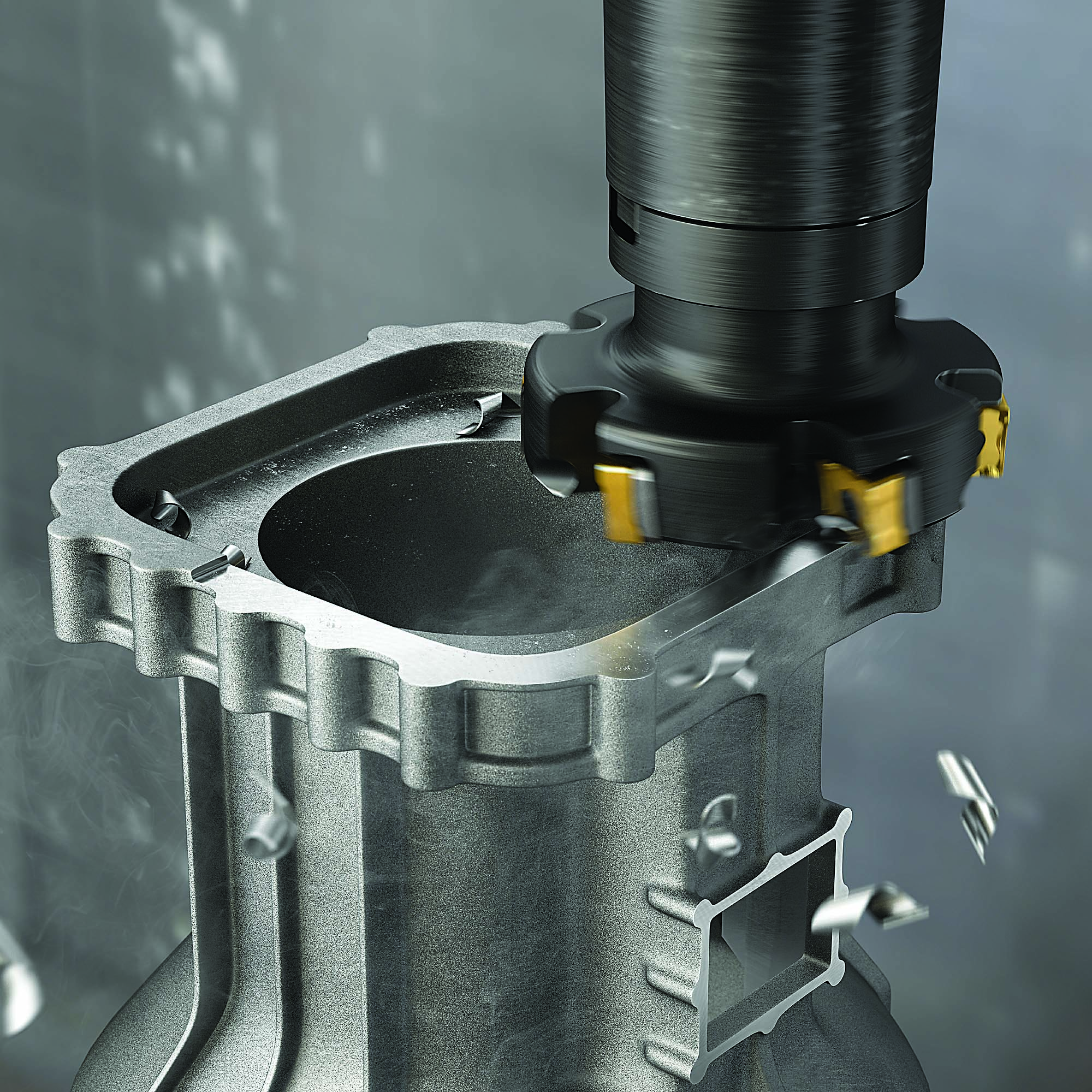
Automotive manufacturers must strive to outperform the competition when machining more complex, near-net-shape parts from tough ISO P materials. Achieving this depends on the choice of cutting tool. For instance, cutting tools with 90-degree lead angles generate radial cutting forces and importantly transfer more cutting energy away from a part. This is ideal when machining parts with thinner walls or near net shapes.
This brings us to shoulder milling, a basic yet versatile milling application recommended for producing a variety of components and when there is a large amount of material to be removed quickly from a workpiece. With shoulder milling, the tool simultaneously creates a plane and shoulder surface, which is why a 90-degree angle to the workpiece is preferred. Other angles can be used depending on the application, but it’s essential that the right angle is used to avoid unwanted offsets between the cutter and workpiece.
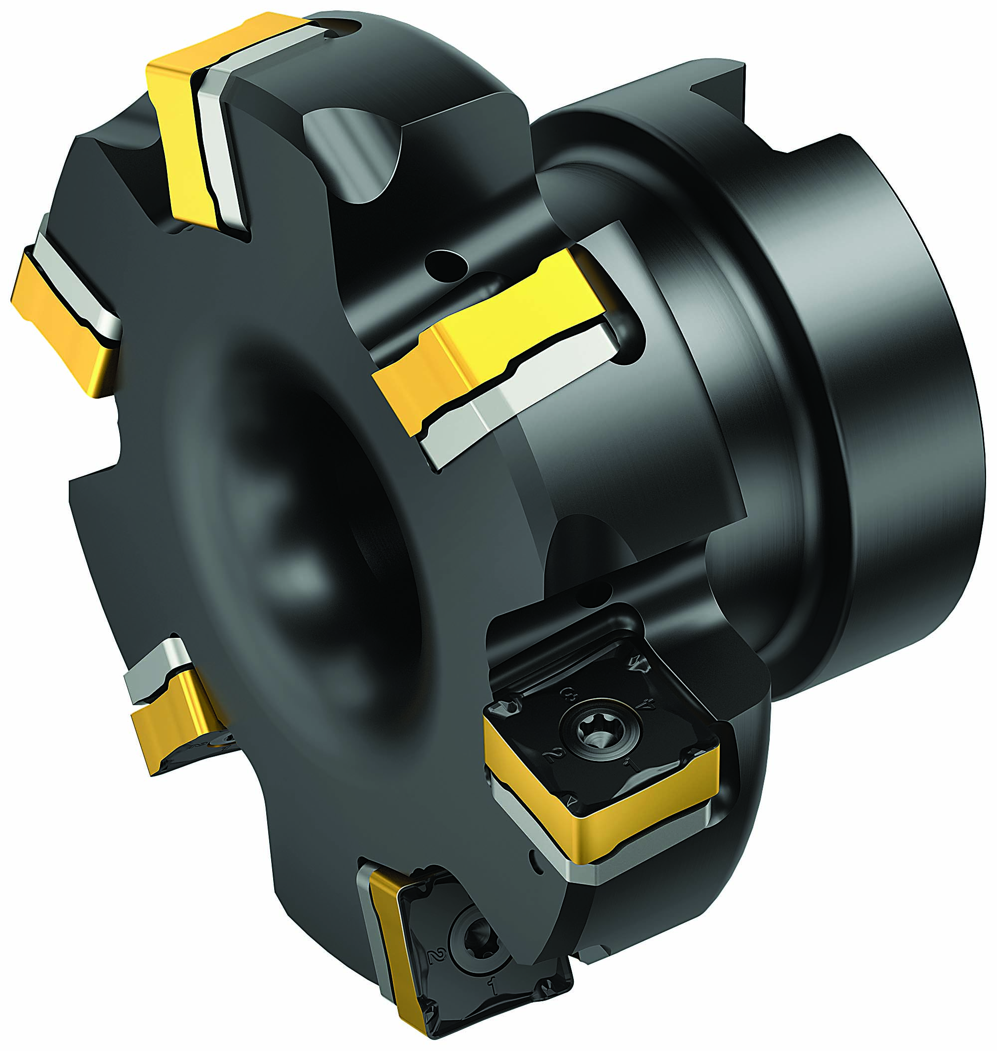
A number of shoulder milling tooling inserts are on the market designed for a nearly 90-degree milling angle. These inserts generally have eight edges ― four on the front and four on the back to simultaneously produce the shoulder and plane ― or six in some cases. However, Sandvik Coromant Co.’s tooling specialists thought that there was room for a new shoulder milling concept that brings tool life, productivity and economic benefits to customers.
The result is CoroMill MF80, which is designed for automotive milling applications in ISO K and ISO P materials. The inserts have eight cutting edges, chip protection and optimized microgeometry for better security and chip evacuation, as well as a wiper edge for superior surface finish. The cutting edge is inclined for smooth cutting action and low cutting forces, making the insert ideal for thin-walled components and machine setups with limited stability. Based on a technology platform similar to the existing CoroMill 345, this new milling concept offers a 40% lighter cutter body with shim protection and a high number of inserts for secure, stable machining, even in vibration-prone overhang
applications.
The 89.5-degree approach angle enables the multi-edge cutter to work close to the fixture while machining. The nearly 90-degree angle also reduces axial forces for improved milling on thin-walled components and weak fixtures without vibration and chatter. This not only improves accuracy and machine utilization but ensures longer tool life with less scrap.
Performance Tests
The performance of CoroMill MF80 has been tested against competing mills when machining ISO K and ISO P materials. Let’s look first at the ISO K performance test, in which the competing tool and CoroMill MF80 each were used in a roughing application to produce carriers and supports from an ISO K spheroidal graphite iron (GJS400/K3.1.C.UT) workpiece.
Both tools were run with the same cutting data, including a spindle speed (n) of 1,000 rpm, a cutting speed (vc) of 250 m/min. and a table feed (vf) of 1,200 mm/min. Each mill was run with a 20-mm-to-80-mm radial depth of cut (ae) and 2-mm-to-3-mm axial DOC (ap). There was a slight difference in feed per tooth (fz): 0.24 mm for the competing mill and 0.3 mm for CoroMill MF80.
In the end, the competing mill produced 10 components in 55 minutes before showing signs of wear. CoroMill MF80, on the other hand, ran for 82 minutes and
produced 15 components in that time. The result for the customer was increased tool life of 54% using Sandvik Coromant’s mill.
In another example, CoroMill MF80 ran against a competing mill in a rough shoulder milling application to produce pump and valve components from an ISO P carbon steel (DIN 1.0619) workpiece. Again, the mills were run with identical cutting data ― an n of 500 rpm, a vc of 125 m/min., an ae of 15 mm to 50 mm, an ap of 5 mm and an fz of 0.15 mm ― with one exception: the vf. The competing mill ran at 375 mm/min., and CoroMill MF80 ran at 600 mm/min.
In this instance, the competing mill produced nine components while CoroMill MF80 produced 15, a productivity increase of 60%. Also, after 40 minutes of machining, only chipping wear was visible on CoroMill MF80, which increased tool life by 67%. For the customer, the key advantage was that CoroMill MF80’s shim protection and the high number of insert edges could lower the cost per part in roughing and shoulder milling applications. Processes like these will be essential in helping manufacturers produce vehicles that meet stringent CO2 emission regulations while maintaining a lower cost per part.
Contact Details
Related Glossary Terms
- approach angle
approach angle
Angle between the insert’s side-cutting edge and the line perpendicular to the milling cutter’s axis of rotation. Approach angle, which is also known as cutting edge angle, is used with metric units of measurement. See lead angle.
- chatter
chatter
Condition of vibration involving the machine, workpiece and cutting tool. Once this condition arises, it is often self-sustaining until the problem is corrected. Chatter can be identified when lines or grooves appear at regular intervals in the workpiece. These lines or grooves are caused by the teeth of the cutter as they vibrate in and out of the workpiece and their spacing depends on the frequency of vibration.
- cutting speed
cutting speed
Tangential velocity on the surface of the tool or workpiece at the cutting interface. The formula for cutting speed (sfm) is tool diameter 5 0.26 5 spindle speed (rpm). The formula for feed per tooth (fpt) is table feed (ipm)/number of flutes/spindle speed (rpm). The formula for spindle speed (rpm) is cutting speed (sfm) 5 3.82/tool diameter. The formula for table feed (ipm) is feed per tooth (ftp) 5 number of tool flutes 5 spindle speed (rpm).
- depth of cut
depth of cut
Distance between the bottom of the cut and the uncut surface of the workpiece, measured in a direction at right angles to the machined surface of the workpiece.
- feed
feed
Rate of change of position of the tool as a whole, relative to the workpiece while cutting.
- fixture
fixture
Device, often made in-house, that holds a specific workpiece. See jig; modular fixturing.
- gang cutting ( milling)
gang cutting ( milling)
Machining with several cutters mounted on a single arbor, generally for simultaneous cutting.
- milling
milling
Machining operation in which metal or other material is removed by applying power to a rotating cutter. In vertical milling, the cutting tool is mounted vertically on the spindle. In horizontal milling, the cutting tool is mounted horizontally, either directly on the spindle or on an arbor. Horizontal milling is further broken down into conventional milling, where the cutter rotates opposite the direction of feed, or “up” into the workpiece; and climb milling, where the cutter rotates in the direction of feed, or “down” into the workpiece. Milling operations include plane or surface milling, endmilling, facemilling, angle milling, form milling and profiling.
- milling machine ( mill)
milling machine ( mill)
Runs endmills and arbor-mounted milling cutters. Features include a head with a spindle that drives the cutters; a column, knee and table that provide motion in the three Cartesian axes; and a base that supports the components and houses the cutting-fluid pump and reservoir. The work is mounted on the table and fed into the rotating cutter or endmill to accomplish the milling steps; vertical milling machines also feed endmills into the work by means of a spindle-mounted quill. Models range from small manual machines to big bed-type and duplex mills. All take one of three basic forms: vertical, horizontal or convertible horizontal/vertical. Vertical machines may be knee-type (the table is mounted on a knee that can be elevated) or bed-type (the table is securely supported and only moves horizontally). In general, horizontal machines are bigger and more powerful, while vertical machines are lighter but more versatile and easier to set up and operate.
- wiper
wiper
Metal-removing edge on the face of a cutter that travels in a plane perpendicular to the axis. It is the edge that sweeps the machined surface. The flat should be as wide as the feed per revolution of the cutter. This allows any given insert to wipe the entire workpiece surface and impart a fine surface finish at a high feed rate.
Author

Based in Sandviken, Sweden, Sangram Dash is global product application manager for indexable milling at Sandvik Coromant Co. in Mebane, North Carolina. For more information, call 800-726-3845 or visit www.sandvik.coromant.com.
