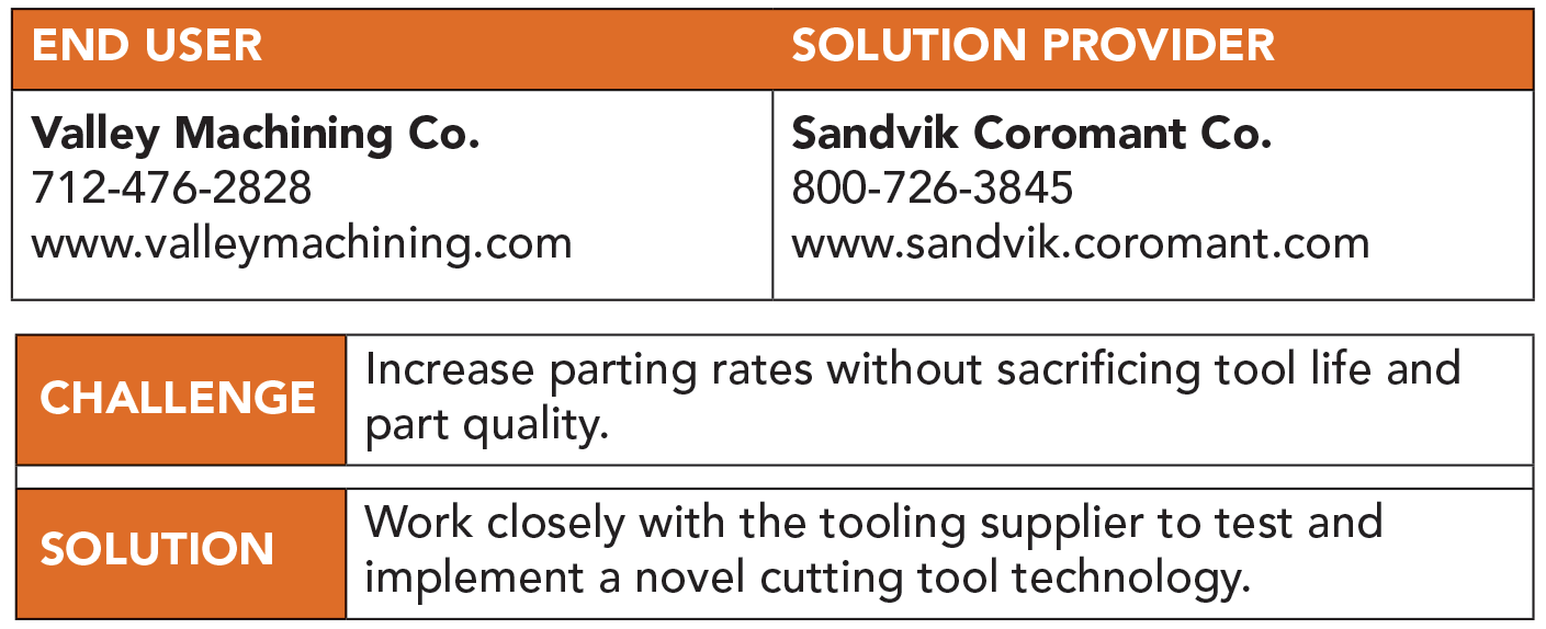
Whether baking a soufflé or trying to beat a red light, timing is everything. So when Brent Schelske, process improvement engineer at Valley Machining Co., Rock Valley, Iowa, stumbled across an advertisement on the Fair Lawn, New Jersey-based Sandvik Coromant Co.’s website for a new kind of parting tool, he immediately contacted the company.
VMC was established in 1980 when founders Len Van Otterloo and Chuck Ver Steeg opened a small machine shop that specialized in multiple-spindle turning. The company has since grown to 85 employees and 100,000 sq. ft. of manufacturing space while serving customers worldwide.
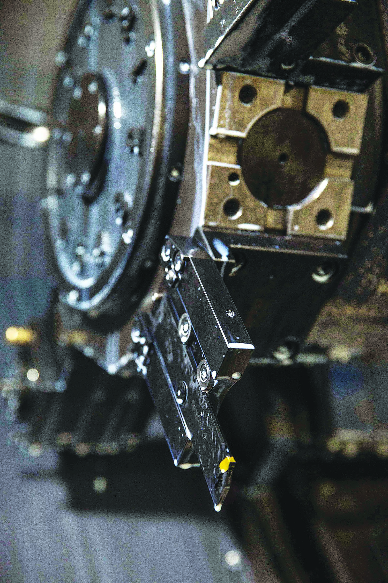
Valley Machining experiences up to 600 percent improvement in cutoff efficiency with Sandvik Coromant’s Y-axis parting tool, according to Process Improvement Engineer Brent Schelske. Image courtesy of Valley Machining
The Wickmans and New Britains on which the business was built are still present, but now there are half a dozen machining centers and more than 20 CNC lathes, many of them twin-spindle multiturret machines with live tools and Y-axis turning capabilities. It was one of these twin-spindle machines that motivated Schelske to contact Sandvik Coromant.
“I was looking something up for a job I was working on, and this video popped up on the screen talking about Y-axis parting,” Schelske said. “And I thought to myself, ‘That’s weird. I wonder if it really works like they say it does.’ Then at the same time, I started thinking about our twin-spindle lathes. You’re always trying to balance the cycle time on one side to the other so as to achieve the greatest productivity. But when you’re cutting off, both spindles are occupied and any improvement is an immediate overall gain. I quite literally called our local tooling distributor about two minutes after seeing the video.”
The video was about the CoroCut QD for Y-axis parting. Compared with conventional parting tools, whose X-axis movement directs the bulk of cutting forces downward against a relatively weak, unsupported blade, Y-axis parting drives most of the cutting forces along the long axis of the blade and toward the tool block. Results are longer tool life, finer surface finishes and significantly higher feed rates.
Days after Schelske viewed the video, he and Tooling Engineer Lyle Schneider headed to the shop floor to work with the parting blade. They encountered a few hurdles, however. The lathe was a Doosan Puma TT2500SY with a 3" bar capacity, an LNS Sprint 12' bar feeder and a 1,000-psi MP Systems high-pressure coolant unit—one of two such machines at VMC. Schelske removed his old cutoff blade and mounted the new one in an extended-length WTO tool block. But he realized he would have to modify the arrangement to utilize the through-the-tool coolant, a must for the parting tool to be applied at anywhere near the advertised feed rates.
Although that problem was not a big deal, another problem was almost disastrous.
“We did some light parting to test things out,” Schelske said. “And then I said, ‘OK, everything looks good. Let’s give it a whirl.’ The second I hit cycle start, the blade slammed into the workpiece at 3,000 rpm. I’d forgotten that with G96 constant surface speed engaged, the control is normally looking at the X-axis position to calculate the correct rpm value. But with Y-axis parting, the tool is positioned on the X-axis centerline, so of course it shot up to the maximum rpm.”
Fortunately, the tool survived. Schelske then tried programming the cutoff operation in multiple steps, gradually increasing the rpm as the Y-axis approached center. Results were not satisfactory. After searching the machine manual for a parameter that would tell the control to recognize the Y-axis rather than the X-axis for rpm calculations, he called his machine distributor for help.
“The guy didn’t get it at first,” Schelske said. “‘Why on earth would you want to do that?’ he asked. I wasn’t sure how to explain it, so I sent him the link to the Y-axis video. He did some digging and found the correct value to change. After that, it was seamless.”
In low-carbon steel, such as 12L14 and cold-drawn (CD) 1018, the CoroCut QD achieves a feed rate of 0.016 ipr at 600 sfm. In 4140 alloy steel, the tool is routinely fed at 0.012 ipr and 500 sfm. By comparison, Schelske typically ran his old cutoff tool at only 0.004 to 0.005 ipr at 400 sfm, depending on the material.
“I used the mean spindle speed in relation to the feed rate when determining rough estimates for the gains we’ve made,” Schelske said. “With low-carbon steels, we’re hovering around a 500 to 600 percent improvement. Resulfurized steels, such as CD 1144, see a 300 to 400 percent gain. And we’re in the same ballpark with A36 structural steel. The smallest gain we’ve seen ranges from 200 to 300 percent, and that’s with CD 1045 material.”
Considering that VMC produces 70,000 parts per year from 2.75"-dia. 4140 bar stock, the ability to triple feed rates is a big win. Another win is tool life. The team consistently gets upward of 500 pieces per insert on that high-volume work, with equally impressive results elsewhere.
“I think Sandvik Coromant hits the nail on the head when they talk about redirecting the vector forces to be in line with the blade,” Schelske said. “I love trying new products and new ways of doing things, but this has been easily the most substantial improvement that I’ve seen from any single cutting tool. I’m constantly dragging people over to show them the Y-axis parting. The response is always, ‘Wow!’”
The only downside Schelske sees with the new technology is that—because Y-axis parting uses such a high feed rate—there is little chance of saving the blade if something goes awry.
“You have to pay attention to your tool life,” Schelske said. “With traditional parting operations, you can push a tool that’s borderline. But wait too long before changing the insert with Y-axis parting and you’ll end up with a melted blob. We went through our fair share of blades at first, but everything has calmed down by this point.”
Related Glossary Terms
- baking
baking
1. Heating to a low temperature to remove gases. 2. Curing or hardening surface coatings, such as paints, by exposure to heat. 3. Heating to drive off moisture, as in the baking of sand cores after molding. Often used after plating or welding, or when the presence of hydrogen is suspected, to prevent embrittlement.
- centers
centers
Cone-shaped pins that support a workpiece by one or two ends during machining. The centers fit into holes drilled in the workpiece ends. Centers that turn with the workpiece are called “live” centers; those that do not are called “dead” centers.
- chuck
chuck
Workholding device that affixes to a mill, lathe or drill-press spindle. It holds a tool or workpiece by one end, allowing it to be rotated. May also be fitted to the machine table to hold a workpiece. Two or more adjustable jaws actually hold the tool or part. May be actuated manually, pneumatically, hydraulically or electrically. See collet.
- computer numerical control ( CNC)
computer numerical control ( CNC)
Microprocessor-based controller dedicated to a machine tool that permits the creation or modification of parts. Programmed numerical control activates the machine’s servos and spindle drives and controls the various machining operations. See DNC, direct numerical control; NC, numerical control.
- coolant
coolant
Fluid that reduces temperature buildup at the tool/workpiece interface during machining. Normally takes the form of a liquid such as soluble or chemical mixtures (semisynthetic, synthetic) but can be pressurized air or other gas. Because of water’s ability to absorb great quantities of heat, it is widely used as a coolant and vehicle for various cutting compounds, with the water-to-compound ratio varying with the machining task. See cutting fluid; semisynthetic cutting fluid; soluble-oil cutting fluid; synthetic cutting fluid.
- cutoff
cutoff
Step that prepares a slug, blank or other workpiece for machining or other processing by separating it from the original stock. Performed on lathes, chucking machines, automatic screw machines and other turning machines. Also performed on milling machines, machining centers with slitting saws and sawing machines with cold (circular) saws, hacksaws, bandsaws or abrasive cutoff saws. See saw, sawing machine; turning.
- cutoff blade
cutoff blade
Blade mounted on a shank or arbor and held in a milling-machine spindle for simple cutoff tasks.
- feed
feed
Rate of change of position of the tool as a whole, relative to the workpiece while cutting.
- lathe
lathe
Turning machine capable of sawing, milling, grinding, gear-cutting, drilling, reaming, boring, threading, facing, chamfering, grooving, knurling, spinning, parting, necking, taper-cutting, and cam- and eccentric-cutting, as well as step- and straight-turning. Comes in a variety of forms, ranging from manual to semiautomatic to fully automatic, with major types being engine lathes, turning and contouring lathes, turret lathes and numerical-control lathes. The engine lathe consists of a headstock and spindle, tailstock, bed, carriage (complete with apron) and cross slides. Features include gear- (speed) and feed-selector levers, toolpost, compound rest, lead screw and reversing lead screw, threading dial and rapid-traverse lever. Special lathe types include through-the-spindle, camshaft and crankshaft, brake drum and rotor, spinning and gun-barrel machines. Toolroom and bench lathes are used for precision work; the former for tool-and-die work and similar tasks, the latter for small workpieces (instruments, watches), normally without a power feed. Models are typically designated according to their “swing,” or the largest-diameter workpiece that can be rotated; bed length, or the distance between centers; and horsepower generated. See turning machine.
- low-carbon steels
low-carbon steels
Group of carbon steels designated by American Iron and Steel Institute numerical classification as AISI 1005, 1006, 1008, etc., up to AISI 1026, for a total of 16 grades. They are softer and more ductile than other carbon steels. Composition of low-carbon steels is 0.06 to 0.28 percent carbon, 0.25 to 1.00 percent manganese, 0.040 percent (maximum) phosphorus and 0.050 percent (maximum) sulfur. See high-carbon steels; medium-carbon steels.
- parting
parting
When used in lathe or screw-machine operations, this process separates a completed part from chuck-held or collet-fed stock by means of a very narrow, flat-end cutting, or parting, tool.
- turning
turning
Workpiece is held in a chuck, mounted on a face plate or secured between centers and rotated while a cutting tool, normally a single-point tool, is fed into it along its periphery or across its end or face. Takes the form of straight turning (cutting along the periphery of the workpiece); taper turning (creating a taper); step turning (turning different-size diameters on the same work); chamfering (beveling an edge or shoulder); facing (cutting on an end); turning threads (usually external but can be internal); roughing (high-volume metal removal); and finishing (final light cuts). Performed on lathes, turning centers, chucking machines, automatic screw machines and similar machines.
Author
News items authored by Cutting Tool Engineering have been written or edited by the editors of Cutting Tool Engineering magazine. The reports represent material submitted to CTE by outside authors, and edited by CTE editors for style and accuracy.