|
Powder metallurgy (PM) was originally valued for its ability to produce parts to near-net shape. The process of pressing powder into molds and then sintering the powder under heat and pressure can yield a part dimensionally accurate enough to use without any subsequent processing. Designers soon discovered, however, that sintered steel had other properties that made it preferable to wrought steel, and so the use of PM materials expanded. As a result, an increasing number of PM parts are being made with complex geometries. But geometrical features such as threads, angular grooves, undercuts, and holes cannot be pressed into PM components with modern die compaction. They must be machined instead. This growing need to machine powder metals has made the machinability of these materials an increasingly important issue. The metalworking industry generally considers powder metals such as sintered steel parts to be less machinable than their wrought counterparts. Powder-processing companies are trying to improve machinability so that their products are competitive in terms of machining costs. Better machinability leads to lower machining costs because a material that is more machinable takes less time to machine and operators waste less time changing tools. Before machinability can be studied, however, there must be some agreement on what the term “machinability” means. Machinability is a difficult property to quantify. Researchers might observe a number of factors to determine whether one material is more machinable than another. They might compare power consumption, material-removal rates, tool wear, torque, thrust, surface roughness, or tool life. With PM materials, the question of machinability is further complicated by the nature of the materials themselves. One factor that significantly influences the machinability of a PM material is its porosity. The more porous the material, the harder it is to machine. Porosity causes noncontinuous contact between the workpiece and the cutting edge of the tool. The result is decreased machinability because of higher tool wear. The more pores there are or the more irregularly shaped they are, the greater their effect on machinability. The cutting characteristics of sintered steel can be controlled by altering the microstructure by means of small additions of other substances to a standard powder composition. For example, machinability can be improved slightly by adding a minimal amount of copper or phosphorus to round the misshapen pores. These additives also increase the speed of sintering and strengthen the material, enabling sintered steel to be produced at low temperatures that still rival the strength and elongation of wrought alloys. Manganese sulfide (MnS) as well as sulfur, selenium, tellurium, and molybdenum disulfide have also been used to promote machinability. Unlike the other additives, however, MnS causes little dimensional change of parts during sintering. With the help of Hoeganaes Corp., Riverton, NJ, researchers at Lehigh University, Bethlehem, PA, initiated a drill test to characterize the machinability of different PM compositions based on tool life. Machinability was based at first on the number of holes drilled and then on torque and thrust. After determining the machinability of each material, the researchers attempted to correlate their findings with the macrostructures and microstructures of the chips, as well as to the additives in each material. Different PM Variations Tested
Before the experiment was conducted, Hoeganaes Corp. provided some data about mechanical properties for the different mixes. The data that concerned this experiment were extrapolated from the known values found in Table 2. Data from Hoeganaes Corp. on such properties as hardness were then confirmed in the experiment.
Each material was pressed into a number of pucks 4" in diameter and 1" deep. Sixty holes were drilled in each puck in the same pattern. The researchers took chip samples from every 20th hole that was drilled. Each test was continued until the drill failed or the pucks prepared from the material were consumed. The drilling conditions were held constant for all seven mixes. The conditions were chosen to reflect typical drilling practices in the field. The drill material was HSS with a black-oxide coating. Each drill was ground with a standard 118° included angle and a diameter of ¼". The researchers ensured the accuracy of the test by choosing intermediate speeds and feed rates. The rotational speed was 2220 rpm, the cutting speed was 145.3 sfm, and the feed rate was 0.005 ipr (11.1 ipm). No cutting fluid was used because the researchers feared that, by improving machinability, the use of cutting fluid would interfere with the results. Following the drilling tests, the researchers examined the first chip sample along with the 40th hole in each puck. To examine the chips under a light optical microscope and a stereomicroscope, the researchers mounted the specimens, ground and polished them, and then etched them in 4% Picral for 90 seconds. Machinability Varied
|
|||||||||||||||||||||||||||||||||||||||||||||||||||||||||||||||||||||||||||||||||||||||||||||
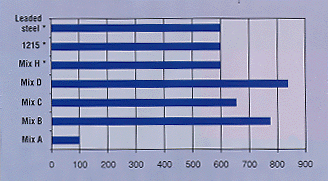 |
| Figure 1: Number of holes drilled before failure. (*Only 600 holes were drilled because that was all the material that was available.) |
|
As an alternative to tool wear, the researchers considered the torque and thrust measurements that were taken during the drilling test (Table 3). High torque and thrust seem to indicate poor machinability, since the tool is working harder to cut the material. When they looked at the torque and thrust data for the three materials that did not cause the drill to fail, they saw that Mix H had the best numbers. They then compared the data from Mix H to the data from Mix D and found that the drilling test with Mix D yielded even better torque and thrust than Mix H. The variation in torque and thrust for Mix D indicated that the material could have been machined for much longer than Mix H before the drill failed. From this data, the researchers concluded that Mix D had the best machinability.
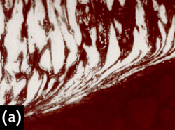
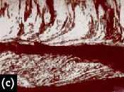
In addition to analyzing the physical data, the researchers examined the chips under a stereomicroscope and a light optical microscope. They studied macrographs of chip samples of Mix D after 20, 400, and 700 holes. They found that as more holes are drilled, the chips get smaller and their color becomes bluer. This blue appearance comes from heat generated as tool wear increases and more torque and thrust are needed to complete the drilling process. The researchers also studied micrographs of the chip samples. Figure 2 shows that Mix D has the normal pearlite and ferrite microstructure, but there is also another phase present. The researchers have not identified this phase yet, but they will study it in more detail in later experiments. Because this soft third phase did not exist in the other microstructures, the researchers assumed it was the reason Mix D was more machinable than the other samples. Like the other materials, Mix D included additives to improve machinability, but it also included a low-alloy steel. The improvement in machinability may be due to the change in the steel’s microstructure, but further inspection of this mix is needed to prove this. |
||||||||||||||||||||||||||||||||||||||||||||||||||||||||||||||||||||||||||||||||
 |
 |
 |
Figure 2: Micrograph of the chip at 573x after 20 holes (a), 400 holes (b), and 700 holes (c). All were etched in 4% Picral for 90 sec. |
|
The researchers concluded that machinability can be improved by the use of additives such as MnS as well as by changes in the microstructure similar to that of Mix D. The test results show that both Mix D and Mix H have machinability that is very close to wrought steel. Further study will prove that PM materials can have similar or better machinability than their wrought counterparts. About the Authors The authors thank Amy Graham and A. Davall of Hoeganaes Corp. The authors also thank Arlan O. Benscoter for all his help with the metallography and his practical wisdom and Kathleen Repa for all her help with scanning electron microscopy. |
Related Glossary Terms
- alloys
alloys
Substances having metallic properties and being composed of two or more chemical elements of which at least one is a metal.
- cutting fluid
cutting fluid
Liquid used to improve workpiece machinability, enhance tool life, flush out chips and machining debris, and cool the workpiece and tool. Three basic types are: straight oils; soluble oils, which emulsify in water; and synthetic fluids, which are water-based chemical solutions having no oil. See coolant; semisynthetic cutting fluid; soluble-oil cutting fluid; synthetic cutting fluid.
- cutting speed
cutting speed
Tangential velocity on the surface of the tool or workpiece at the cutting interface. The formula for cutting speed (sfm) is tool diameter 5 0.26 5 spindle speed (rpm). The formula for feed per tooth (fpt) is table feed (ipm)/number of flutes/spindle speed (rpm). The formula for spindle speed (rpm) is cutting speed (sfm) 5 3.82/tool diameter. The formula for table feed (ipm) is feed per tooth (ftp) 5 number of tool flutes 5 spindle speed (rpm).
- elongation
elongation
In tensile testing, the increase in the gage length, measured after fracture of the specimen within the gage length, usually expressed as a percentage of the original gage length.
- feed
feed
Rate of change of position of the tool as a whole, relative to the workpiece while cutting.
- ferrite
ferrite
Solid solution of one or more elements in body-centered cubic iron. Unless otherwise designated, for instance, as chromium ferrite, the solute is generally assumed to be carbon. On an equilibrium diagram, there are two ferrite regions separated by an austenite area. The lower area is alpha ferrite and the upper area is delta ferrite. If there is no designation, alpha ferrite is assumed. Not more than 0.04 percent carbon can be dissolved in alpha iron. Ferrite is stable below 1,670º F (910º C); it is soft, highly ductile, and magnetic. Ferrite loses its magnetic property above 1,414º F (768º C).
- hardness
hardness
Hardness is a measure of the resistance of a material to surface indentation or abrasion. There is no absolute scale for hardness. In order to express hardness quantitatively, each type of test has its own scale, which defines hardness. Indentation hardness obtained through static methods is measured by Brinell, Rockwell, Vickers and Knoop tests. Hardness without indentation is measured by a dynamic method, known as the Scleroscope test.
- high-speed steels ( HSS)
high-speed steels ( HSS)
Available in two major types: tungsten high-speed steels (designated by letter T having tungsten as the principal alloying element) and molybdenum high-speed steels (designated by letter M having molybdenum as the principal alloying element). The type T high-speed steels containing cobalt have higher wear resistance and greater red (hot) hardness, withstanding cutting temperature up to 1,100º F (590º C). The type T steels are used to fabricate metalcutting tools (milling cutters, drills, reamers and taps), woodworking tools, various types of punches and dies, ball and roller bearings. The type M steels are used for cutting tools and various types of dies.
- included angle
included angle
Measurement of the total angle within the interior of a workpiece or the angle between any two intersecting lines or surfaces.
- lapping compound( powder)
lapping compound( powder)
Light, abrasive material used for finishing a surface.
- machinability
machinability
The relative ease of machining metals and alloys.
- mechanical properties
mechanical properties
Properties of a material that reveal its elastic and inelastic behavior when force is applied, thereby indicating its suitability for mechanical applications; for example, modulus of elasticity, tensile strength, elongation, hardness and fatigue limit.
- metalworking
metalworking
Any manufacturing process in which metal is processed or machined such that the workpiece is given a new shape. Broadly defined, the term includes processes such as design and layout, heat-treating, material handling and inspection.
- microstructure
microstructure
Structure of a metal as revealed by microscopic examination of the etched surface of a polished specimen.
- pearlite
pearlite
Lamellar aggregate of ferrite and cementite in slowly cooled iron-carbon alloys occurring normally as a principle constituent of steel and cast iron. Fully annealed steel containing 0.85 percent carbon consists entirely of pearlite.
- powder metallurgy
powder metallurgy
Processes in which metallic particles are fused under various combinations of heat and pressure to create solid metals.
- sawing machine ( saw)
sawing machine ( saw)
Machine designed to use a serrated-tooth blade to cut metal or other material. Comes in a wide variety of styles but takes one of four basic forms: hacksaw (a simple, rugged machine that uses a reciprocating motion to part metal or other material); cold or circular saw (powers a circular blade that cuts structural materials); bandsaw (runs an endless band; the two basic types are cutoff and contour band machines, which cut intricate contours and shapes); and abrasive cutoff saw (similar in appearance to the cold saw, but uses an abrasive disc that rotates at high speeds rather than a blade with serrated teeth).
- sintering
sintering
Bonding of adjacent surfaces in a mass of particles by molecular or atomic attraction on heating at high temperatures below the melting temperature of any constituent in the material. Sintering strengthens and increases the density of a powder mass and recrystallizes powder metals.