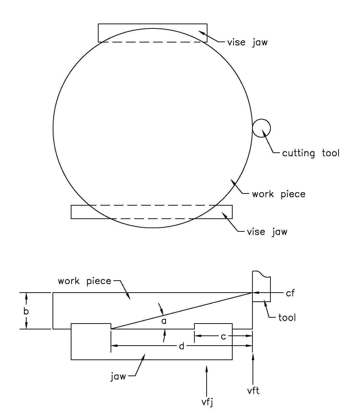
In my previous column, I went through how to hold an 11"-dia.-by-2"-thick workpiece on a 6" milling vise. This column will showcase a little math to estimate forces involved with aggressive metal removal. In this way, it is possible to machine economically and safely. The drawing shows the problem.
This 190-cubic-inch piece of stock is going to turn into a 75-cubic-inch finished part. To begin, 40 cubic inches will be removed from the outside diameter above where the part is clamped in the vise. When roughing, I use corncob endmills that have little bumps on the flutes, but the math that I use is adaptable to whatever tools you like.
In the drawing, when the tool moves laterally into the workpiece or moves radially around the workpiece center, it will make tangential cutting force CF, which will resolve itself into a horizontal and a vertical component determined by angle a. At the tool, that produces vertical force VFT, which is CF tan a, or CF times a/d. The important thing to consider is the vertical force at the vise jaw clamping surface VFJ, which is higher than VFT because of mechanics. VFJ equals VFT times d/d-c.
If VFJ gets close to the vertical holding power of the clamping surface, then there will be trouble. In the article about the vise jaws for this part, it was determined that 3,600 lbs. of vertical force could be resisted by the steel back jaw holding this aluminum part. There are two clamping surfaces on this jaw, so that’s 1,800 lbs. per surface.
Cutting speed and chip thickness are best determined the normal way to maximize tool economy, but the depth and width of cut can be adjusted for good, safe metal removal.
Determining CF is the key to the puzzle. The tensile strength of the workpiece with the size and number of the chips will give a useful number.
CF = TGNHJR/W
Where
T = tensile strength of the
workpiece
G = width of the chips (for some tools, this is the depth of cut)
H = chip thickness
J = (number of flutes)/2
R = tool radius
W = horizontal width of cut
If
T = 40,000
G = 0.125
H = 0.01
N = 8
J = 2
R = 0.5
W = 0.65
Then CF = 800 lbs.
This has worked for me. It’s overkill in most situations, and of course it can be improved. But it gives a relationship between workpiece tensile strength and metal removal rate, and it’s quick and easy to use.
One thing more: If your cutting tool has a helix angle, the cutting force produces a vertical force pulling the part out of the vise and the endmill out of its holder. If you know CF, you can estimate this force too. Safety pays.
Related Glossary Terms
- cutting force
cutting force
Engagement of a tool’s cutting edge with a workpiece generates a cutting force. Such a cutting force combines tangential, feed and radial forces, which can be measured by a dynamometer. Of the three cutting force components, tangential force is the greatest. Tangential force generates torque and accounts for more than 95 percent of the machining power. See dynamometer.
- cutting speed
cutting speed
Tangential velocity on the surface of the tool or workpiece at the cutting interface. The formula for cutting speed (sfm) is tool diameter 5 0.26 5 spindle speed (rpm). The formula for feed per tooth (fpt) is table feed (ipm)/number of flutes/spindle speed (rpm). The formula for spindle speed (rpm) is cutting speed (sfm) 5 3.82/tool diameter. The formula for table feed (ipm) is feed per tooth (ftp) 5 number of tool flutes 5 spindle speed (rpm).
- endmill
endmill
Milling cutter held by its shank that cuts on its periphery and, if so configured, on its free end. Takes a variety of shapes (single- and double-end, roughing, ballnose and cup-end) and sizes (stub, medium, long and extra-long). Also comes with differing numbers of flutes.
- flutes
flutes
Grooves and spaces in the body of a tool that permit chip removal from, and cutting-fluid application to, the point of cut.
- gang cutting ( milling)
gang cutting ( milling)
Machining with several cutters mounted on a single arbor, generally for simultaneous cutting.
- helix angle
helix angle
Angle that the tool’s leading edge makes with the plane of its centerline.
- milling
milling
Machining operation in which metal or other material is removed by applying power to a rotating cutter. In vertical milling, the cutting tool is mounted vertically on the spindle. In horizontal milling, the cutting tool is mounted horizontally, either directly on the spindle or on an arbor. Horizontal milling is further broken down into conventional milling, where the cutter rotates opposite the direction of feed, or “up” into the workpiece; and climb milling, where the cutter rotates in the direction of feed, or “down” into the workpiece. Milling operations include plane or surface milling, endmilling, facemilling, angle milling, form milling and profiling.
- tensile strength
tensile strength
In tensile testing, the ratio of maximum load to original cross-sectional area. Also called ultimate strength. Compare with yield strength.
- width of cut
width of cut
Width of the milled surface, reflecting a face milling cutter’s radial engagement, and a peripheral milling cutter’s axial engagement, in the cut.
Author

Brandt Taylor is owner of Berlin, Massachusetts-based Taylor Engineering, a machine shop.
