Gas turbines propel planes and helicopters, tanks, ships and locomotives. The largest turbines can be found in natural-gas power plants that produce electricity for homes and businesses.
At the heart of a gas turbine is a rotor with hundreds of individual airfoils called blades. Blades are arranged circumferentially around a disc, and several discs are stacked together to make a single rotor. Discs are held in place with special bolts and nuts.
At Mitsubishi Hitachi Power Systems Americas Inc., we refer to the hardware as spindle bolts and spindle nuts. These nuts and bolts exert enormous forces on the discs and must last for hundreds of thousands of hours in extremely harsh environments. Therefore, thread quality is critical to the life of both the spindle hardware and the gas turbine rotors.
Spindle bolts are made from difficult-to-machine, high-strength superalloys. They have very tight dimensional tolerances, which makes thread cutting a challenge. As a result of facing several thread-cutting problems during process development, we have learned important lessons at Mitsubishi.
Multiple Configurations
Threads are made in many configurations, typically to a recognized specification like the Unified National. UN and other standards dictate the size and shape of internal and external threads. Engineers usually reference a standard in their designs, but it is not unheard of to be asked to manufacture a nonstandard thread, which is the case with spindle bolts.
All images courtesy of C. Tate.
UN thread dimensions are given as proportional values based on the pitch or distance between threads. All thread dimensions can be found in a number of reference materials and are not usually provided on the part print. In our situation, we had a UN designation, but the drawing included specific dimensions. Investigation revealed we did not have a UN thread. This prevented us from using a standard thread-cutting tool, because stock tools are made to cut dimensions and geometries given by specifications like the UN standard. Therefore, we were forced to purchase a special carbide threading insert.
After resolving the thread form issue and having the special made, we discovered that our spindle bolt workpiece material was difficult to machine. Initial test cuts produced chatter that could wake the dead. Spindle bolts are long, relative to their diameter. This length makes all machining operations difficult. Because the threads are always cut near a supported area, we decided the tool itself must be producing the chatter.
For any other turning operation, the machinist could adjust the feed rate to put more pressure on the tool to minimize chatter. Because threads require a fixed feed rate to generate the proper pitch, we could not adjust the feed rate. Instead, we lowered the cutting speed. However, when we reached the point where the chatter stopped, the cutting speed was very low and the cycle time was unacceptable. Therefore, changing the cutting speed was not the solution.
Strategic Switch
Success was finally reached when we changed the machining strategy. A CNC lathe allows the programmer to enter the thread-cutting cycle in one of three ways: leading edge only, alternating between leading and trailing edges, or straight in so both leading and trailing edges cut simultaneously.
We had initially arranged the program to cut on the leading edge only, which is the traditional way to set up a lathe for threading. Increasing tool pressure often reduces chatter. However, cutting on the leading edge lowers cutting pressures, thereby causing chatter. We changed the program so the tool would plunge straight in and cut with both sides of the insert. This adjustment increased the pressure enough to eliminate the chatter.
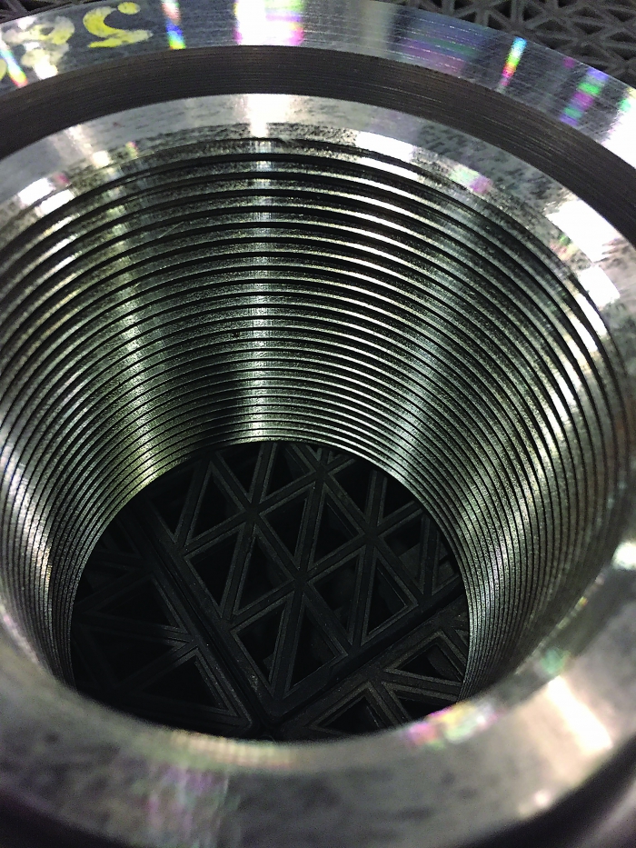
A spindle nut with an odd thread geometry.
After resolving the chatter issue, we found out just how difficult the bolt material was to machine. Our first attempts to cut the threads were dismal; we were unable to complete the threading cycle before insert failure. After investigation, we determined that the cutting speed was too high and, thus, generated too much heat. We also discovered that the coolant was not mixed to the proper concentration. The lack of lubricity resulted in excessive chip welding on the cutting edge, or built-up edge. To overcome these problems, we reduced the cutting speed and increased the coolant concentration. This allowed us to complete the threading cycle.
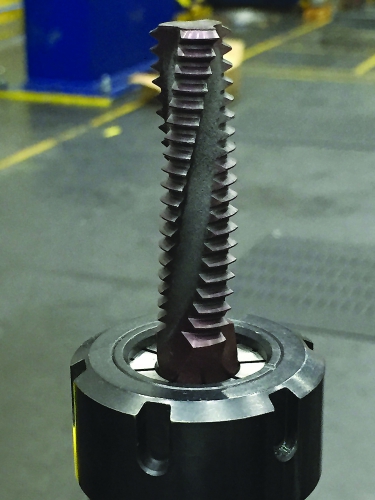
This tool is for thread milling spindle nuts.
Milling Threads
Nuts for the spindle bolts were the next challenge. Nuts are made from material that is much easier to machine, but the thread geometry is difficult to generate. We also had to produce precise start and stop locations for the threads.
Our first attempt to manufacture the nuts was done on a horizontal turning center, which is traditionally used to manufacture these parts. We made a complete set of nuts and installed them in the turbine. However, the start and stop locations of the threads made producing them a painful process.
Going forward with the nuts, we plan on thread milling them, which will provide significant advantages. Thread milling will let us accurately and easily deliver the desired start and stop locations for the threads. In the lathe, we first mark the jaws with a scribe line. We then align the machined features to the line to ensure that the start location for the thread is correct. The machining center allows us to program the start point of the threads, so aligning features will no longer be necessary.
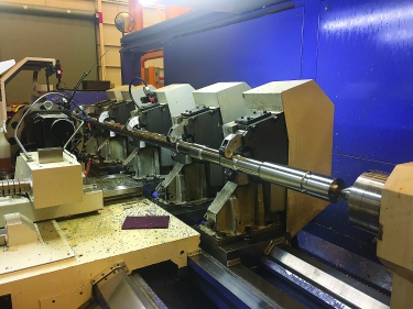
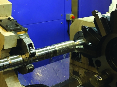
This lathe is used to manufacture Mitsubishi Hitachi’s spindle bolts. Difficult-to-machine alloys and the large length-to-diameter ratio make machining a challenge. All surface finishes are critical, but having a good finish on the threads is particularly so.
Next, we will eliminate the lathe setup. The initial machining process required three setups: twoon the vertical machining center and one on the lathe. Our new process will be done on a horizontal machining center, eliminating the cost of setup on the lathe and reducing the lead time for the part.
The main issue with thread milling is the cost of the tools, which are specials. Fortunately, they should last a long time, and the reduction in setup and lead times should justify the extra cost.
Making threads can frustrate the most-experienced machinists. But threading problems can be overcome with the right information, guidance and some research.
Related Glossary Terms
- alloys
alloys
Substances having metallic properties and being composed of two or more chemical elements of which at least one is a metal.
- built-up edge ( BUE)
built-up edge ( BUE)
1. Permanently damaging a metal by heating to cause either incipient melting or intergranular oxidation. 2. In grinding, getting the workpiece hot enough to cause discoloration or to change the microstructure by tempering or hardening.
- chatter
chatter
Condition of vibration involving the machine, workpiece and cutting tool. Once this condition arises, it is often self-sustaining until the problem is corrected. Chatter can be identified when lines or grooves appear at regular intervals in the workpiece. These lines or grooves are caused by the teeth of the cutter as they vibrate in and out of the workpiece and their spacing depends on the frequency of vibration.
- computer numerical control ( CNC)
computer numerical control ( CNC)
Microprocessor-based controller dedicated to a machine tool that permits the creation or modification of parts. Programmed numerical control activates the machine’s servos and spindle drives and controls the various machining operations. See DNC, direct numerical control; NC, numerical control.
- coolant
coolant
Fluid that reduces temperature buildup at the tool/workpiece interface during machining. Normally takes the form of a liquid such as soluble or chemical mixtures (semisynthetic, synthetic) but can be pressurized air or other gas. Because of water’s ability to absorb great quantities of heat, it is widely used as a coolant and vehicle for various cutting compounds, with the water-to-compound ratio varying with the machining task. See cutting fluid; semisynthetic cutting fluid; soluble-oil cutting fluid; synthetic cutting fluid.
- cutting speed
cutting speed
Tangential velocity on the surface of the tool or workpiece at the cutting interface. The formula for cutting speed (sfm) is tool diameter 5 0.26 5 spindle speed (rpm). The formula for feed per tooth (fpt) is table feed (ipm)/number of flutes/spindle speed (rpm). The formula for spindle speed (rpm) is cutting speed (sfm) 5 3.82/tool diameter. The formula for table feed (ipm) is feed per tooth (ftp) 5 number of tool flutes 5 spindle speed (rpm).
- feed
feed
Rate of change of position of the tool as a whole, relative to the workpiece while cutting.
- gang cutting ( milling)
gang cutting ( milling)
Machining with several cutters mounted on a single arbor, generally for simultaneous cutting.
- lathe
lathe
Turning machine capable of sawing, milling, grinding, gear-cutting, drilling, reaming, boring, threading, facing, chamfering, grooving, knurling, spinning, parting, necking, taper-cutting, and cam- and eccentric-cutting, as well as step- and straight-turning. Comes in a variety of forms, ranging from manual to semiautomatic to fully automatic, with major types being engine lathes, turning and contouring lathes, turret lathes and numerical-control lathes. The engine lathe consists of a headstock and spindle, tailstock, bed, carriage (complete with apron) and cross slides. Features include gear- (speed) and feed-selector levers, toolpost, compound rest, lead screw and reversing lead screw, threading dial and rapid-traverse lever. Special lathe types include through-the-spindle, camshaft and crankshaft, brake drum and rotor, spinning and gun-barrel machines. Toolroom and bench lathes are used for precision work; the former for tool-and-die work and similar tasks, the latter for small workpieces (instruments, watches), normally without a power feed. Models are typically designated according to their “swing,” or the largest-diameter workpiece that can be rotated; bed length, or the distance between centers; and horsepower generated. See turning machine.
- lubricity
lubricity
Measure of the relative efficiency with which a cutting fluid or lubricant reduces friction between surfaces.
- machining center
machining center
CNC machine tool capable of drilling, reaming, tapping, milling and boring. Normally comes with an automatic toolchanger. See automatic toolchanger.
- milling
milling
Machining operation in which metal or other material is removed by applying power to a rotating cutter. In vertical milling, the cutting tool is mounted vertically on the spindle. In horizontal milling, the cutting tool is mounted horizontally, either directly on the spindle or on an arbor. Horizontal milling is further broken down into conventional milling, where the cutter rotates opposite the direction of feed, or “up” into the workpiece; and climb milling, where the cutter rotates in the direction of feed, or “down” into the workpiece. Milling operations include plane or surface milling, endmilling, facemilling, angle milling, form milling and profiling.
- pitch
pitch
1. On a saw blade, the number of teeth per inch. 2. In threading, the number of threads per inch.
- superalloys
superalloys
Tough, difficult-to-machine alloys; includes Hastelloy, Inconel and Monel. Many are nickel-base metals.
- threading
threading
Process of both external (e.g., thread milling) and internal (e.g., tapping, thread milling) cutting, turning and rolling of threads into particular material. Standardized specifications are available to determine the desired results of the threading process. Numerous thread-series designations are written for specific applications. Threading often is performed on a lathe. Specifications such as thread height are critical in determining the strength of the threads. The material used is taken into consideration in determining the expected results of any particular application for that threaded piece. In external threading, a calculated depth is required as well as a particular angle to the cut. To perform internal threading, the exact diameter to bore the hole is critical before threading. The threads are distinguished from one another by the amount of tolerance and/or allowance that is specified. See turning.
- turning
turning
Workpiece is held in a chuck, mounted on a face plate or secured between centers and rotated while a cutting tool, normally a single-point tool, is fed into it along its periphery or across its end or face. Takes the form of straight turning (cutting along the periphery of the workpiece); taper turning (creating a taper); step turning (turning different-size diameters on the same work); chamfering (beveling an edge or shoulder); facing (cutting on an end); turning threads (usually external but can be internal); roughing (high-volume metal removal); and finishing (final light cuts). Performed on lathes, turning centers, chucking machines, automatic screw machines and similar machines.
Author

Christopher Tate is the owner of Tate Engineering, a Natchez, Mississippi, firm that helps manufacturers solve efficiency problems. Tate, who earned master's degree in industrial technology from Mississippi State University, has 32 years of experience in the metalworking industry.