How should shops choose an indexable insert for a cutting application? In many cases, probably not the way the choice actually is made.
Instead of just going with the familiar, the right approach is to take a comprehensive look at the cutting process at hand and then select an insert with the right characteristics to meet the demands and requirements of that application. Insert suppliers can be a big help in this regard. Their experts can steer you toward an insert that not only is suitable for a particular job but will help optimize productivity and tool life.
Before beginning the process of zeroing in on the right insert, shops should consider whether a removable cutting tip is a better choice for a job than a solid tool. One of the main attractions of inserts is that they normally have more than one cutting edge. When worn, a cutting edge can be changed by turning or flipping the insert, also known as indexing, to an unused edge.
On the downside, however, indexable inserts are not as rigid as solid tools and thus not as accurate.
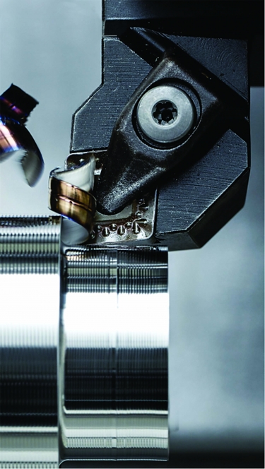
Choosing the right insert for an application can increase productivity and tool life. Image courtesy of Ceratizit USA
“You can’t match the tolerance or finish of a ground surface with an insert because of deflection,” said Jim White, national sales manager at Carmex Precision Tools LLC in Richfield, Wisconsin.
Therefore, he said, most indexable milling cutters are roughers and finishing is done with solid tools like endmills.
For turning, “everything is indexable,” White said, and tight tolerances can be held. But this typically requires both a rougher and finisher. Moreover, the finisher can’t be indexed often because each indexing results in a loss of accuracy. That’s why many finishing inserts are single-sided as opposed to double-sided inserts that can be flipped over, he said.
Then there’s the issue of cost.
“Most smaller shops always ask for an indexable solution because they think it is cheaper than a solid tool,” White said.
He said although this is true in theory, in many cases indexable inserts break or wear quickly.
Carmex Precision Tools sells both indexable and solid thread mills. For low-volume jobs, White believes that a solid is the better choice. But for high-volume production, he thinks that an indexable is more economical over the life of the job. Besides being more expensive than an indexable, he noted, a solid must be resharpened, after which tool life drops by about 30%. In addition, he pointed out that solids must have their coatings stripped and then be re-coated — with a coating that is never as good as the original. So for high-volume jobs, he usually recommends an indexable.
Starting the Process
Once the decision is made to go with an indexable insert, shops face the task of choosing from many options. A good way to start the selection process is to decide what you want to achieve with the insert, said Jan Andersson, product manager for indexable inserts at YG-1 Tool (USA) Co. in Vernon Hills, Illinois. While productivity might be the top priority at some shops, he said, others may place a higher value on flexibility and prefer an insert that can be used to machine multiple types of similar components.
Another early consideration in the insert selection process should be the application — in particular, the material to be machined.
“Modern cutting tools are material-specific,” Andersson said. “So you can’t necessarily select an insert grade that is performing well in steel and assume that it’s also going to work well in stainless, superalloys or aluminum.”
Tool manufacturers offer a wide range of insert grades — from more wear-resistant to tougher — and geometries to handle a variety of materials, as well as material conditions like hardness and whether a material is cast or forged.
“If you have a cast or forged component, your grade selection will be different than it would be if you’re (cutting) a clean or pre-machined material,” Andersson said. “In addition, geometry selection for a cast component will be different than it would be for a pre-machined component.”
Shops also should take into account the machine or machines in which an insert will be used.
“Some machines have horsepower limitations, and some have spindle rpm limitations,” said Justin Messerschmidt, technical manager for cutting tools at Ceratizit USA Inc. in Warren, Michigan. “If you don’t take those into consideration, you could choose a carbide grade that needs to run at a higher rpm to be successful but not be able to achieve that because of the machine limitations.”
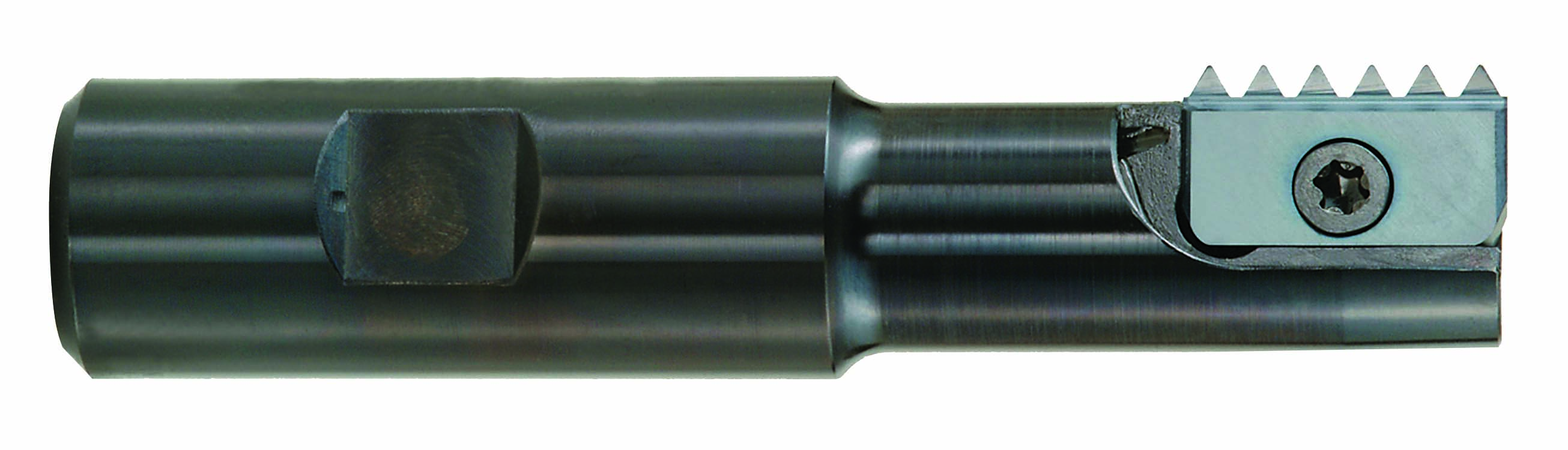
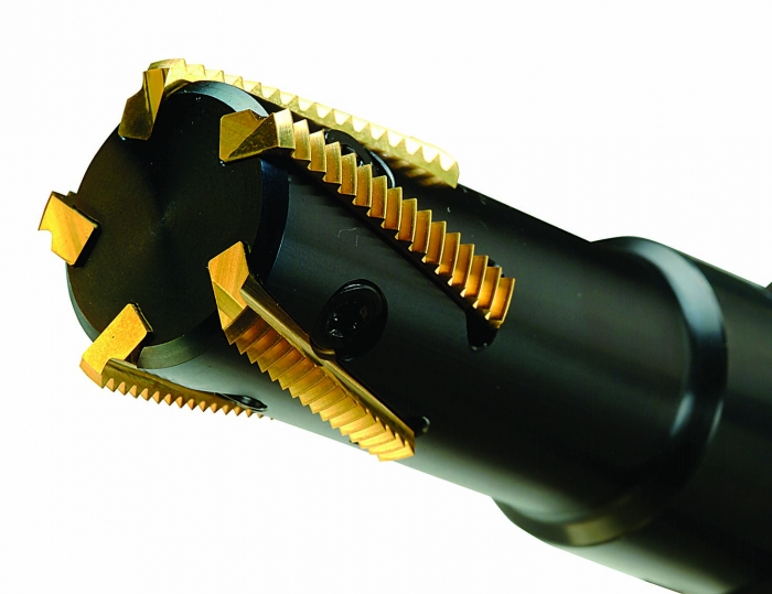
Helical-flute indexable thread mills (bottom) run faster and more efficiently than straight-flute indexable thread mills (top) while usually wearing much less as well. Image courtesy of Carmex Precision Tools
In addition to machine capabilities, shops should look at the entire machining setup and evaluate its rigidity and stability. This includes the stability of the machine itself, as well as the toolholding and workholding.
“If you can’t clamp a good portion of the part,” Messerschmidt said, “you wouldn’t choose an insert with a larger radius because that could (increase) tool pressure, which would cause chatter or lift the part out of the workholding.”
He said if the toolholding or workholding setup isn’t rigid, there is a good chance that the result will be chatter.
“And if you have chatter and you’ve chosen an insert substrate that is too hard,” Messerschmidt said, “you have a situation that is much more prone to insert failure.”
Hard Versus Tough
This illustrates an important but counterintuitive fact about insert selection: The hardest, most wear-resistant insert substrate is not always the best choice for an application. Consider, for example, a situation in which an insert must be chosen to cut forged material with hard spots in it.
“The harder the insert, the more brittle it is,” Messerschmidt said. “So running into a difficult portion of cut could cause catastrophic insert failure.”
Similarly, Andersson said, the most wear-resistant grade is probably not the right choice for applications with unstable setups.
Instead, “you will probably have to go to a tougher grade to manage vibration introduced by the instabilities,” he said.
Another important factor in grade selection is the machining speed of an application.
“You want a grade that matches up to the speed you intend to run at,” Andersson said.
Generally, he said, the idea is to run as fast as possible for maximum productivity but not so fast that the speed significantly reduces tool life.
Messerschmidt said not using the correct speed and feed with a particular insert can result in poor surface finish and chip control. He added that an increased feed rate is required for inserts with larger nose radiuses. Ordinarily, he said, the larger the nose radius, the higher the feed rate should be.
“If there is chatter, the natural inclination is to turn down the feed rate,” he said. “But that’s actually the opposite of what you should do in this case. If you don’t use an increased feed rate with a larger nose radius, you could get chatter and poor surface finishes.”
Common Mistakes
When it comes to mistakes in the selection of inserts, Andersson points to a number of common errors. One is concentrating first on choosing the best grade for an application and only afterward considering the geometries available for that grade.
“Never separate grade from geo-metry because you can utilize geometry to reinforce grade,” he said.
Consider, for instance, the toughness of an insert.
“You can measure mechanical toughness properties, but that doesn’t really matter much,” Andersson said. “What matters is how the combination of grade and geometry behaves in the end user’s machine. And if you pick a very strong geometry, you will gain toughness behavior.”
Geometry considerations can include insert microgeometry, or edge line condition, as well as what he refers to as macrogeometry, which is the shape or topography of the top side of the insert. The latter typically is called the chipbreaker.
“In any manufacturer’s catalog, you’ll see that for steel, say, you have a choice of a number of different grades and chipbreakers,” Andersson said. “We try to match up the grade with the chipbreaker to get the best solution for an
application.”
Another common mistake he cited is thinking that an insert with more cutting edges is always the best choice. That would mean, for example, that a WNMG insert with six edges is inherently a better option than a four-edge CNMG insert.
“You automatically think that the cost per edge (of the WNMG) is going to be lower,” Andersson said. “But that’s not the case.”
The reason, he explained, is that the way the WNMG is seated in its pocket is a fairly weak arrangement that allows insert movement during machining. The result is vibration, which translates to increased wear and shorter tool life. So in many cases, a CNMG would cut as many parts over time as a WNMG.
Andersson also believes it’s a mistake for shops to ask for an insert that can cut a number of dissimilar materials.
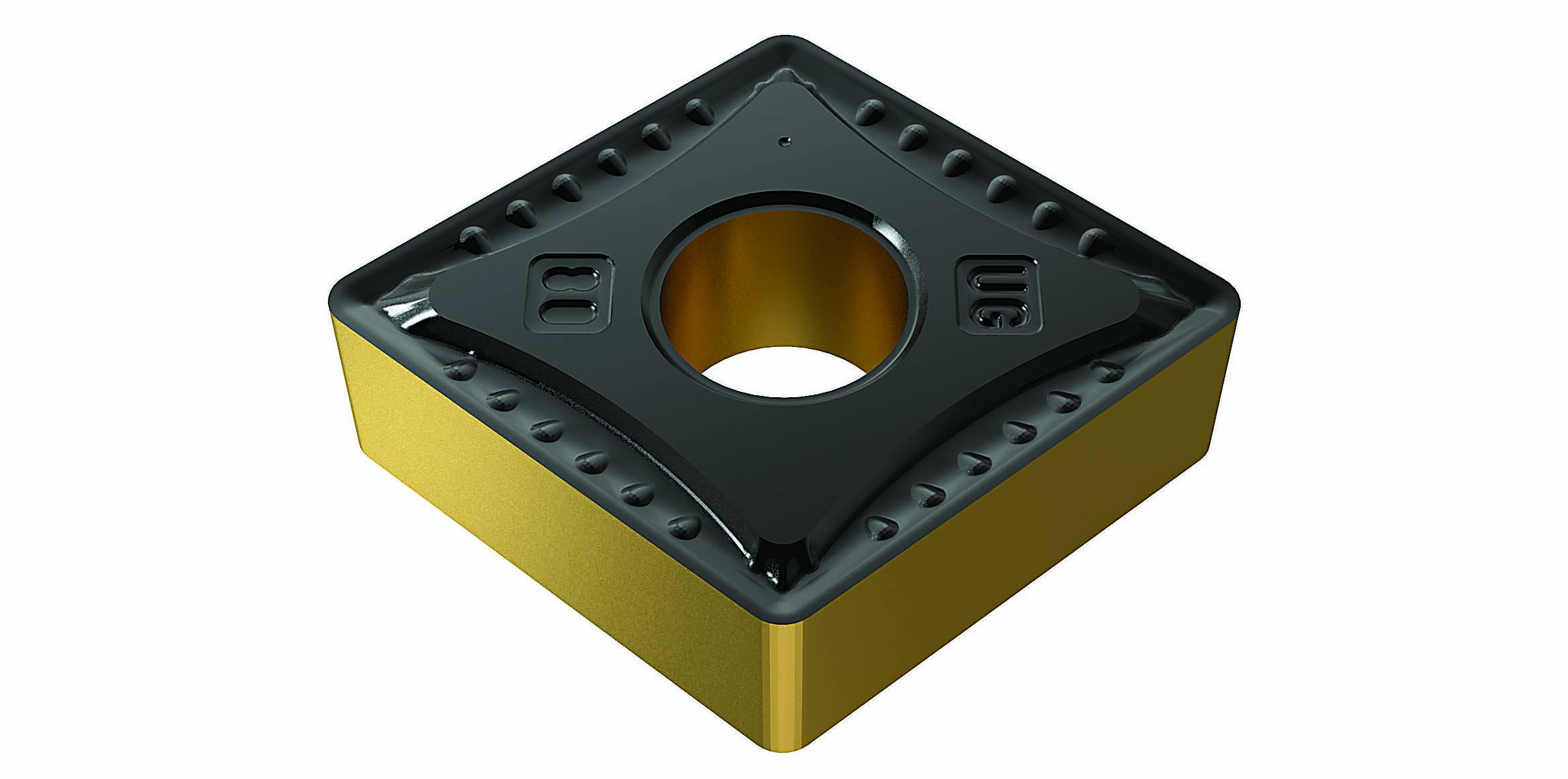
In many cases, four-edge CNMG inserts can cut as many parts as their six-edge WNMG counterparts. Image courtesy of YG-1 Tool (USA)
“The more you use one grade and one geometry for different applications, the more compromises you introduce,” he said. “So you start paying penalties in tool life and chip control, and you are setting yourself up for failure.”
Shops that choose a general-purpose grade and/or chipbreaker also make sacrifices in cycle time, which doesn’t make sense for people trying to optimize processes, Messerschmidt said.
On the other hand, machines at some shops need to be flexible enough to deal with numerous machining scenarios.
“Job shops may want a general-purpose insert because they don’t have the time, resources or inventory capabilities to put in a specific insert for every application on their shelf,” Messerschmidt said.
Help From Suppliers
Whatever its objectives or situation, a shop can get valuable insert selection assistance from tool suppliers. In the COVID-19 environment, however, there are limits to what insert manufacturers can do for customers.
“We have become very good at giving recommendations off-site,” Andersson said, adding that limitations exist from not being able to see customer setups, spot machine vibrations or hear telltale noises, which means that advice comes with an increased safety margin.
In many cases, he would like to provide more help to customers than they actually request.
“The most common question I get is, ‘I am using Brand X, and here is the grade and the geometry. What is your equivalent of that?’” Andersson said.
He refers to this as “cross-referencing” and believes it’s a bad way to start a conversation with an insert supplier. The reason, he said, is that about 90% of the time, people making these requests are using a suboptimal grade and geometry for applications.
“What you should say is, ‘Here is the application, the material, the hardness and the material condition. What do you recommend?’” Andersson said. “You are better off starting fresh with (a recommendation for) the best solution for each application.”
Contact Details

Contact Details
Contact Details

Related Glossary Terms
- chatter
chatter
Condition of vibration involving the machine, workpiece and cutting tool. Once this condition arises, it is often self-sustaining until the problem is corrected. Chatter can be identified when lines or grooves appear at regular intervals in the workpiece. These lines or grooves are caused by the teeth of the cutter as they vibrate in and out of the workpiece and their spacing depends on the frequency of vibration.
- chipbreaker
chipbreaker
Groove or other tool geometry that breaks chips into small fragments as they come off the workpiece. Designed to prevent chips from becoming so long that they are difficult to control, catch in turning parts and cause safety problems.
- feed
feed
Rate of change of position of the tool as a whole, relative to the workpiece while cutting.
- gang cutting ( milling)
gang cutting ( milling)
Machining with several cutters mounted on a single arbor, generally for simultaneous cutting.
- hardness
hardness
Hardness is a measure of the resistance of a material to surface indentation or abrasion. There is no absolute scale for hardness. In order to express hardness quantitatively, each type of test has its own scale, which defines hardness. Indentation hardness obtained through static methods is measured by Brinell, Rockwell, Vickers and Knoop tests. Hardness without indentation is measured by a dynamic method, known as the Scleroscope test.
- indexable insert
indexable insert
Replaceable tool that clamps into a tool body, drill, mill or other cutter body designed to accommodate inserts. Most inserts are made of cemented carbide. Often they are coated with a hard material. Other insert materials are ceramic, cermet, polycrystalline cubic boron nitride and polycrystalline diamond. The insert is used until dull, then indexed, or turned, to expose a fresh cutting edge. When the entire insert is dull, it is usually discarded. Some inserts can be resharpened.
- milling
milling
Machining operation in which metal or other material is removed by applying power to a rotating cutter. In vertical milling, the cutting tool is mounted vertically on the spindle. In horizontal milling, the cutting tool is mounted horizontally, either directly on the spindle or on an arbor. Horizontal milling is further broken down into conventional milling, where the cutter rotates opposite the direction of feed, or “up” into the workpiece; and climb milling, where the cutter rotates in the direction of feed, or “down” into the workpiece. Milling operations include plane or surface milling, endmilling, facemilling, angle milling, form milling and profiling.
- superalloys
superalloys
Tough, difficult-to-machine alloys; includes Hastelloy, Inconel and Monel. Many are nickel-base metals.
- tolerance
tolerance
Minimum and maximum amount a workpiece dimension is allowed to vary from a set standard and still be acceptable.
- turning
turning
Workpiece is held in a chuck, mounted on a face plate or secured between centers and rotated while a cutting tool, normally a single-point tool, is fed into it along its periphery or across its end or face. Takes the form of straight turning (cutting along the periphery of the workpiece); taper turning (creating a taper); step turning (turning different-size diameters on the same work); chamfering (beveling an edge or shoulder); facing (cutting on an end); turning threads (usually external but can be internal); roughing (high-volume metal removal); and finishing (final light cuts). Performed on lathes, turning centers, chucking machines, automatic screw machines and similar machines.
Author

William Leventon is a contributing editor to Cutting Tool Engineering magazine. Contact him by phone at 609-920-3335 or via email at [email protected].
Contributors
Carmex Precision Tools LLC
855-463-5509
www.carmexusa.com
Ceratizit USA Inc.
800-783-2280
www.ceratizit.com
YG-1 Tool (USA) Co.
800-765-8665
www.yg1usa.com