Even low-volume operations producing many different parts can benefit from lights-out production.
As in the book “The Elves and the Shoemaker,” the idea of arriving to work in the morning to find a day’s worth of production already completed sounds too good to be true for many job shops. However, with advances in automation technology, the “fairy tale” of lights-out manufacturing has become a reality, or at least a possibility, for many shops that might not have previously considered it. By studying and understanding specific characteristics of manufacturing processes, automation can be applied to achieve lights-out production even for companies producing small volumes of many different parts. Most stable machining processes can be automated, as can part loading/unloading and other processes.
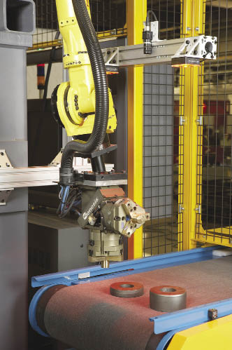
Courtesy of Genesis
This lights-out manufacturing installation operates for up to 4 hours with no operator intervention. It includes a material handling robot (pictured).
Depending upon the processes being automated, the benefits of automation will vary among companies. It is worth evaluating the potential return on investment (ROI) of a project early on to better understand how to implement automation to achieve the best bang for the buck. Often, the scale of an automation project is proportional to the scale of the company and its production volumes. With an in-depth analysis of production processes and goals, an automated concept can be tailored for an application whether the company is large or small.
For example, even the simplest robotic load/unload project will often increase the utilization of existing capital equipment from 60 to around 90 percent. With automatic bulk feeding and a part logistics strategy, that simple system can be enhanced to achieve an unattended multishift operation, essentially pushing the utilization of process equipment beyond what had been regarded as maximum capacity in a single shift.
The benefits of increasing the amount of product coming from a single machine in a given time frame are obvious—more parts in less time for less cost. If automation enables one machine to achieve the throughput of many, the benefits grow beyond the variables considered with a typical ROI calculation.
An automated approach could require less capital equipment and lower operating costs, enabling a company to bid more aggressively with better margins. With existing programs, adding automation could enable equipment to be reapplied to other products or to be setup to exclusively run specific products, eliminating time-consuming changeover. Again, the result is greater profit.
In general, the two largest gains of implementing lights-out production are greater production efficiency and lower labor costs. Added bonuses include predictable production capacity and the ability to adjust production rates without having to modify employee work schedules.
Lights-Out Considerations
Determining whether lights-out production is appropriate begins with an evaluation of the manufacturing process. An automation project can make all the financial sense in the world, but will not succeed if it requires an unsustainable support effort. An evaluation should determine the following.
Is the process stable in that it does not require continuous dimensional “tweaking,” fault recovery, manual tool changes and manual tool offsets?
How often does the process need to be adjusted, manually restarted, cleaned or measured?
Can anyone perform the work now or does it require a specific person?
Sometimes, as in the case of periodic in-process gaging or tool offsets, these issues can be addressed with new equipment; however, if, for example, a CNC turning process is not dimensionally capable, simply adding a robot to it will only exaggerate that problem by removing the person who could solve the recurring problem.
Once a shop determines automation can be successfully applied, it should step back and consider the bigger picture.
• What should the production flow look like?
• How much floor space is available?
• Are parts processed in batches?
• If so, what is the batch size?
• What are the cycle times for each part?
• How many part models does the system need to be capable of handling, and how often will changeover occur?
• What does the incoming and outgoing packaging look like?
These questions differ for every company, but they all require the same type of answer. The goal of the exercise is to fully understand how parts are to arrive and exit the process equipment in the most efficient manner.
Case 1: Gear Making
Consider the example of a gear making division of a large company that makes earth-moving equipment. The gear division makes drivetrain components and wanted to automate a CNC turning operation that took the part from a forging to the final OD/ID prior to gear cutting.
Its product mix is steady and includes 12 models with changeover every three shifts. Cycle times are in the 2-minute range, and frequent tool offsets are required due to tool wear.
An ROI study was performed, and it was determined that adding automation to the lathes would be financially beneficial, assuming a two-shift operation. The turning process was known to be stable because the product was a mature design and had been produced for years using CNC lathes with manual load/unload.
The specifications for the automated system included the following:
• Unattended operation of the two lathes for up to 2 hours
• 100 percent part inspection
• Automatic tool offsets
• Internal six-piece bank for work-in-process (WIP) between lathe operations
• Access to the lathes without stopping the automation
• Automated loading of parts from incoming bulk-loading tubs
• No changeover for the automation
• Automatic delivery to a downstream robot system
• Turnkey programming of the lathes and robot system
• Optional in-process inspection drawer
The automated solution was supplied by Genesis Systems Group, a supplier of robotic arc welding systems, assembly automation systems and robotic tooling and material handling systems, and Hartwig Inc., a machine tool distributor (see illustration on page 39). The automation includes a Fanuc R-2000iA material handling robot that tends two Okuma LU-300 lathes. Randomly oriented, raw forgings are introduced to the cell in tubs by fork truck. A Genesis Bulkpick orients and feeds the parts to the robot. Fanuc’s integrated iRVision-2D finds the parts and offsets the robot’s pick points. This combination of equipment and technologies allows full tubs of parts (up to 300 parts per tub) to be loaded without interrupting production and with no automation changeover among part models. It is possible to run an 8-hour shift’s worth of production lights-out.
The 100 percent part inspection mandate is achieved with an automatic gage that sends tool offset data to the Okuma THINC controller via Autocomp software. This inspection method enables the operator to leave the cell for long periods, returning for manual process checks.
By positioning the lathes back-to-back with the robot between them, the front doors are on the outside of the work cell. If the operator needs to replace a tool insert, for instance, the automation bypasses that lathe and uses the WIP station for in-process parts so that production does not stop. The process now requires only minimal operator intervention.
Case 2: Spare Parts Maker
In another case, the large job shop division that produces spare parts at the same equipment manufacturer was moving the machining of roughly 85 part models of dozens of product types from a room full of special machines to a single Okuma Macturn 550 multifunction lathe with a 180-position toolchanger. In doing so, the number of setups per part decreased from many to one, saving days in the production cycle.
With the combined machining processes, individual cycle times for machining the parts ranged from minutes to hours, depending upon part geometry. Production batch sizes range from one to 50 parts, and the daily production recipe is defined by the plant network.
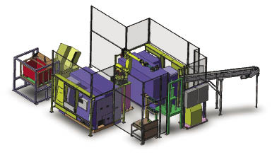
Courtesy of Genesis
This automation system includes a material-handling robot that tends two lathes.
Automated load/unload was considered due to the long cycle time of the machining processes. To meet production demands and maximize machine tool utilization, an operator would spend much of his time waiting for the machine to complete the cycle so he could immediately tend the lathe. If the process wasn’t manually monitored, machining would end and no one would be there to swap parts.
Upon first review of the large number of part models and the small batch sizes, this project appeared destined for manual load; however, once cycle times were factored into the equation, automation became more feasible. Using a strategy that blends random part positioning on incoming conveyors, robot vision and plant network integration to sort production by parts that use the same lathe and robot tooling, a robot was added to the work cell.
At the beginning of each day’s production, parts are randomly loaded onto incoming conveyors per the daily recipe. The robot selects and separates the appropriate part using vision technology and a custom gripper. If required, the robot reorients the raw part automatically prior to loading the MacTurn. Finished parts are placed on an outgoing conveyor or in a manual drawer for coordinate measuring machine checks. In all cases, the robot presents the machined parts to a Telesis part marker, which automatically marks them with a serial number and bar code per input from the plant network.
The number and configuration of incoming and outgoing conveyors was determined so that a sufficient quantity of parts was loaded for the system to run unattended for one shift.
Automation Methods
Once a process is determined to be automation friendly, the focus can be turned to the method of automation. The options can seem endless and sometimes daunting, including:
• gantry vs. robotic load
• flexible vs. hard-tooled
• vision system vs. fixtured
• conveyors vs. pallets
Even if a company has an internal automation group, it is wise to enlist the support of a qualified integrator to help decide how to automate a particular application. Producing the same part continuously with no changeover differs greatly from producing small volumes of a large variety of parts.
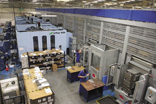
Courtesy of Fastems
A Fastems flexible manufacturing system linked by a 112-position, computer-controlled storage and retrieval system for housing machine pallets and raw materials. It includes five horizontal machining centers.
In cases where a part simply has to be manually loaded into a fixture, a flexible manufacturing system (FMS) might be more applicable than a fully automated production system (see photo below). These systems load entire fixture pallets into and out of machine tools and can be sized to bank a nearly endless number of pallets and tooling. This approach works well for applications involving the following conditions:
• Large parts that exceed robot lifting capacity
• Difficult load procedures that require manual oversight
• Manual fixtures with no automatic clamping
• Complex work flow and/or multiple machines and operations
• Inconsistent batch sizes
With automation technology becoming increasingly sophisticated and flexible, it’s now possible for operations of all sizes to consider lights-out manufacturing. With global competition on the rise, all manufacturing operations—including job shops producing low volumes of multiple products—owe it to themselves to at least consider the possibility of lights-out manufacturing. CTE
About the Author: Whitney Moon is market segment manager, automation systems for Genesis Systems Group, Davenport, Iowa. For more information about the company’s automation and material handling systems, call (563) 445-5685, visit www.genesis-systems.com or enter #350 on the IS Form.
Related Glossary Terms
- centers
centers
Cone-shaped pins that support a workpiece by one or two ends during machining. The centers fit into holes drilled in the workpiece ends. Centers that turn with the workpiece are called “live” centers; those that do not are called “dead” centers.
- computer numerical control ( CNC)
computer numerical control ( CNC)
Microprocessor-based controller dedicated to a machine tool that permits the creation or modification of parts. Programmed numerical control activates the machine’s servos and spindle drives and controls the various machining operations. See DNC, direct numerical control; NC, numerical control.
- fixture
fixture
Device, often made in-house, that holds a specific workpiece. See jig; modular fixturing.
- flexible manufacturing system ( FMS)
flexible manufacturing system ( FMS)
Automated manufacturing system designed to machine a variety of similar parts. System is designed to minimize production changeover time. Computers link machine tools with the workhandling system and peripherals. Also associated with machine tools grouped in cells for efficient production. See cell manufacturing.
- in-process gaging ( in-process inspection)
in-process gaging ( in-process inspection)
Quality-control approach that monitors work in progress, rather than inspecting parts after the run has been completed. May be done manually on a spot-check basis but often involves automatic sensors that provide 100 percent inspection.
- in-process gaging ( in-process inspection)2
in-process gaging ( in-process inspection)
Quality-control approach that monitors work in progress, rather than inspecting parts after the run has been completed. May be done manually on a spot-check basis but often involves automatic sensors that provide 100 percent inspection.
- lathe
lathe
Turning machine capable of sawing, milling, grinding, gear-cutting, drilling, reaming, boring, threading, facing, chamfering, grooving, knurling, spinning, parting, necking, taper-cutting, and cam- and eccentric-cutting, as well as step- and straight-turning. Comes in a variety of forms, ranging from manual to semiautomatic to fully automatic, with major types being engine lathes, turning and contouring lathes, turret lathes and numerical-control lathes. The engine lathe consists of a headstock and spindle, tailstock, bed, carriage (complete with apron) and cross slides. Features include gear- (speed) and feed-selector levers, toolpost, compound rest, lead screw and reversing lead screw, threading dial and rapid-traverse lever. Special lathe types include through-the-spindle, camshaft and crankshaft, brake drum and rotor, spinning and gun-barrel machines. Toolroom and bench lathes are used for precision work; the former for tool-and-die work and similar tasks, the latter for small workpieces (instruments, watches), normally without a power feed. Models are typically designated according to their “swing,” or the largest-diameter workpiece that can be rotated; bed length, or the distance between centers; and horsepower generated. See turning machine.
- recovery
recovery
Reduction or removal of workhardening effects, without motion of large-angle grain boundaries.
- toolchanger
toolchanger
Carriage or drum attached to a machining center that holds tools until needed; when a tool is needed, the toolchanger inserts the tool into the machine spindle. See automatic toolchanger.
- turning
turning
Workpiece is held in a chuck, mounted on a face plate or secured between centers and rotated while a cutting tool, normally a single-point tool, is fed into it along its periphery or across its end or face. Takes the form of straight turning (cutting along the periphery of the workpiece); taper turning (creating a taper); step turning (turning different-size diameters on the same work); chamfering (beveling an edge or shoulder); facing (cutting on an end); turning threads (usually external but can be internal); roughing (high-volume metal removal); and finishing (final light cuts). Performed on lathes, turning centers, chucking machines, automatic screw machines and similar machines.
- vision system
vision system
System in which information is extracted from visual sensors to allow machines to react to changes in the manufacturing process.
Author
News items authored by Cutting Tool Engineering have been written or edited by the editors of Cutting Tool Engineering magazine. The reports represent material submitted to CTE by outside authors, and edited by CTE editors for style and accuracy.