Almost all indexable inserts — estimated at about 90% to 95% — are coated, either with the physical vapor deposition or chemical vapor deposition coating method.
For the CVD process, the base substances used for the coating are vaporized before being supplied to the coating zone, reports toolmaker Ceratizit USA Inc. in Warren, Michigan. The vapor then either decomposes or reacts with additional base substances to produce a thin film on the cutting tool substrate.
In contrast, PVD processes are based on purely physical response methods. A material vapor condenses on the substrate surface, and to ensure that the vapor particles reach the components and are not lost through the dispersion of gas molecules, the process takes place under vacuum conditions.
The differences in the resulting coatings are quite pronounced.
“You cannot compare CVD and PVD because the coating textures and chemistries are different,” said Christoph Czettl, R&D manager of cutting tools for Ceratizit Austria GmbH. “For example, with PVD on the inserts, the most common coating is TiAlN. With CVD, the most frequently used coating architectures are TiCN and aluminum oxide, so those are completely different types of coatings.”
In addition, some solid-carbide, round-shank tools are CVD-coated with diamond, which is a special form of CVD coating.
For example, Sandvik Coromant Co. manufactures its diamond coating using hot filament CVD, a technology that is “totally different” from the one used to manufacture other CVD coatings, said Doug Evans, grade development specialist for Sandvik Coromant’s facility in Mebane, North Carolina. “These technologies cannot be compared.”
With that information in mind, this article focuses on the applications for CVD-coated inserts.
Coating Composition
In addition to TiCN and Al2O3, nondiamond CVD coating materials generally are restricted to TiC and TiN. Although a single-layer CVD coating is possible, virtually all CVD-coated inserts have two or three layers. Brian Wilshire, technical center manager for Kyocera Precision Tools Inc. in Hendersonville, North Carolina, said most of the toolmaker’s CVD-coated grades start with a TiCN layer on the substrate, followed by an Al2O3 layer and topped with TiN.
Unlike PVD coatings, which are composed of multiple layers of coatings a few nanometers thick to achieve a coating that’s from 1 to 7 µm (0.00004" to 0.00028") thick, CVD coatings are usually from 5 to 20 µm (0.0002" to 0.00079") thick and sometimes thicker.
“Typically, the harder, more wear-resistant grades go with a thicker coating,” Wilshire said. “If you are trying to improve toughness, you go with a thinner coating.”
Each layer can have a different thickness, he said, adding that an aluminum oxide layer that’s thicker than the other ones enhances heat and wear resistance.
“The key is making sure the initial coating layer adheres to the carbide and subsequent layers adhere to each other,” Wilshire said. “Obviously, if the coating doesn’t stick to the insert, it’s not going to do you any good.”
Currently in the fundamental stage, Czettl said Ceratizit is researching zirconium-based CVD coatings, such as ZrCN, to replace TiCN. With three other people, he authored a paper that stated that some reports suggest that there are advantageous mechanical and thermal properties of Zr(C,N) over Ti(C,N) coatings. One of the main questions involves costs: Are there deposition rates that make this economical?
Time and Temperature
Reducing the time required to deposit a CVD coating is one way to increase cost efficiency. Czettl said Ceratizit’s target is a deposition rate of better than 2 µm (0.00008") per hour.
“You can push it more,” he said, “but usually there is a trade-off. If you push it too much, you get more scattering in coating thickness.”
Czettl said having a high level of homogeneity is a primary benefit of a CVD coating.
Besides keeping deposition time as short as possible, toolmakers try to keep the coating temperature as low as possible to prevent the process from damaging the carbide substrate, such as by brittling it. However, he said too low of a temperature risks creating adhesion problems.
Rather than producing CVD-coated inserts at a temperature of 1,000 degrees C (1,832 F), which was typical in the past, Wilshire said CVD coatings generally are deposited using the medium-temperature CVD method in which the temperature ranges from about 700 to 950 C (1,292 to 1,742 F).
“Medium-temperature CVD is not going to leach the cobalt as badly,” he said.
Because carbide and coatings have different rates of thermal expansion and contraction, Wilshire said the CVD coatings deposited with the older, high-temperature CVD method tended to develop microcracks. MTCVD helps reduce or eliminate residual cracks in the coating.
“Playing with the coating thickness helps as well,” he said. “The thinner the coating, the less time you are spending in the chamber at the high temperature.”
However, Evans said CVD is not suitable for brazed products because the process still reaches a temperature that melts the brazing. In addition, he said Sandvik Coromant does not offer solid-carbide, round-shank tools with nondiamond CVD coatings because those tools are typically long and slender, especially small-diameter ones, and tend to experience shape deviation at CVD’s elevated temperatures, which is not an issue with PVD.
Crystal Control
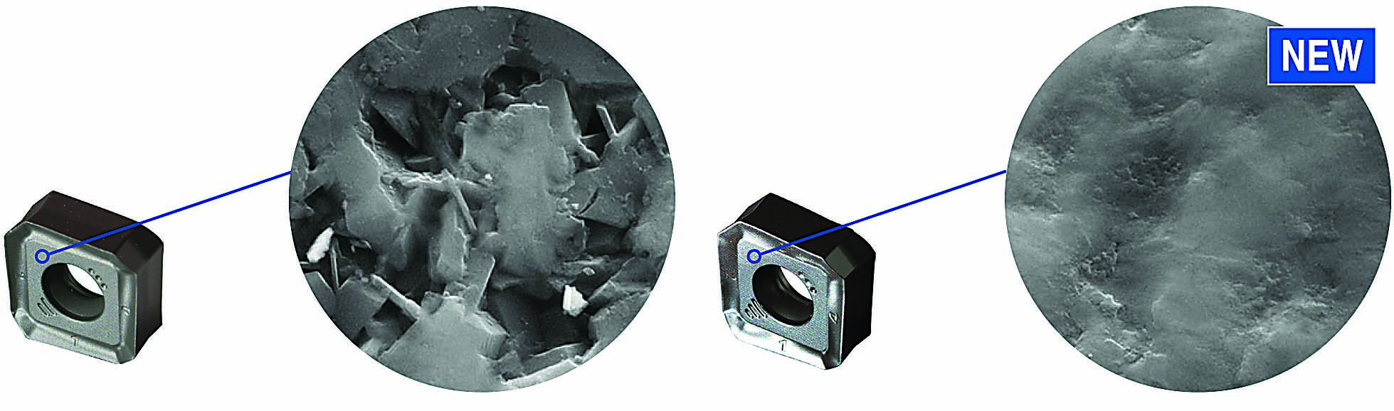
To minimize stresses in the CVD alumina, or Al2O3, coating, Evans said Sandvik Coromant developed a technology called Inveio to control the orientation, or structure, of the crystals in the coating. With the technology, the crystals are arranged in a uniform direction that points toward the cutting edge in a tightly packed structure that improves coating strength and extends tool life 25% to 30%, according to the company. The inserts are aimed at cutting ISO P steel and are suitable for machining stainless steel and cast iron.
Kyocera Precision Tools takes a different approach to tightly controlling the fine-grain structure of its CVD coatings by “continually playing with the compositions of the gases as they are introduced” to the coating chamber, Wilshire explained.
The result is a TiCN layer with a strong columnar shape that’s perpendicular to the top surface of the insert, an alumina layer with tightly aligned small grains, and a top TiN coating where the small grain size enhances stability.
“The end goal is a finer-grain structure with a precise grain alignment to improve the wear resistance, rigidity and toughness of the coatings,” Wilshire said. “If a crack does start, it is more easily arrested instead of letting it run through the coating and down to the substrate itself.”
Areas of Application
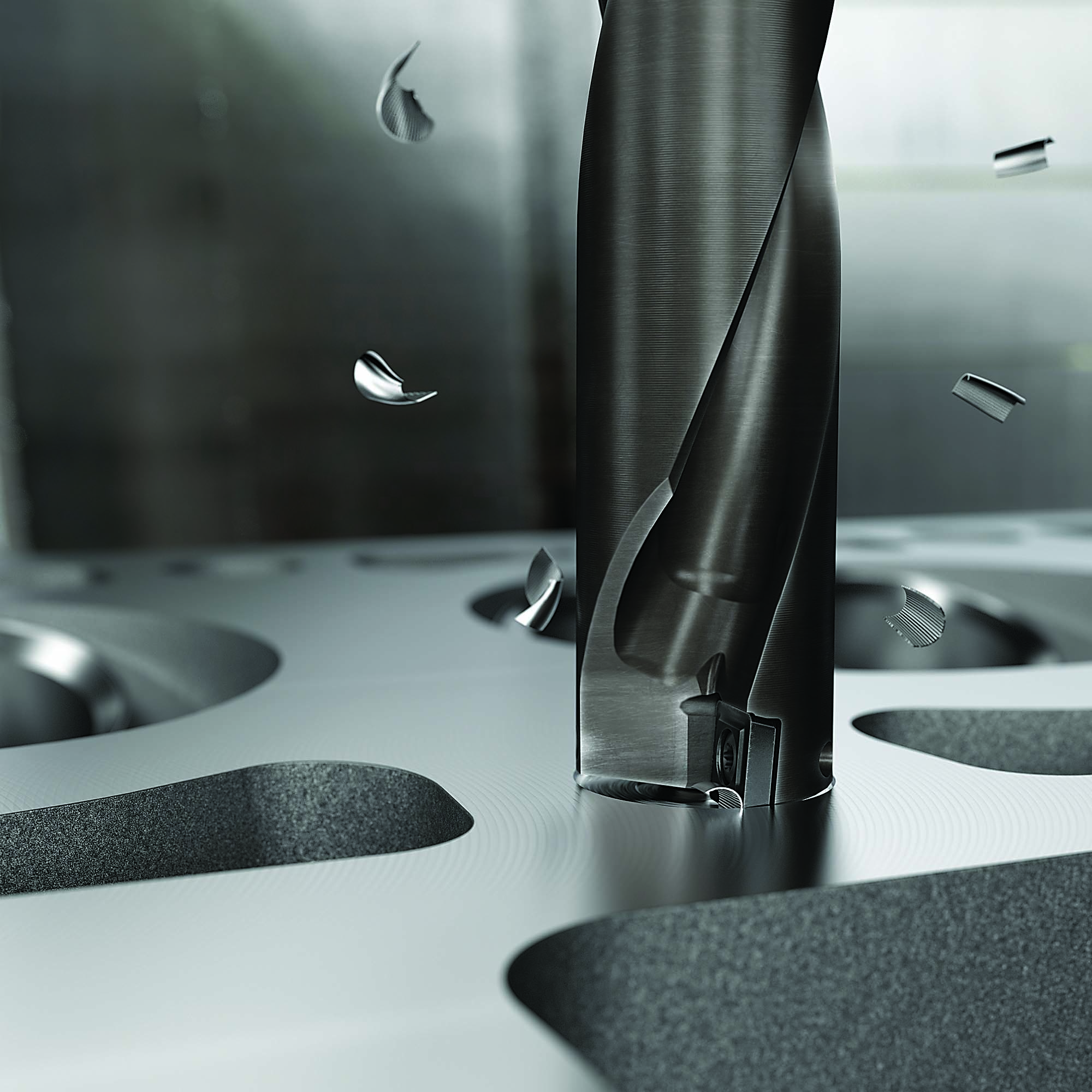
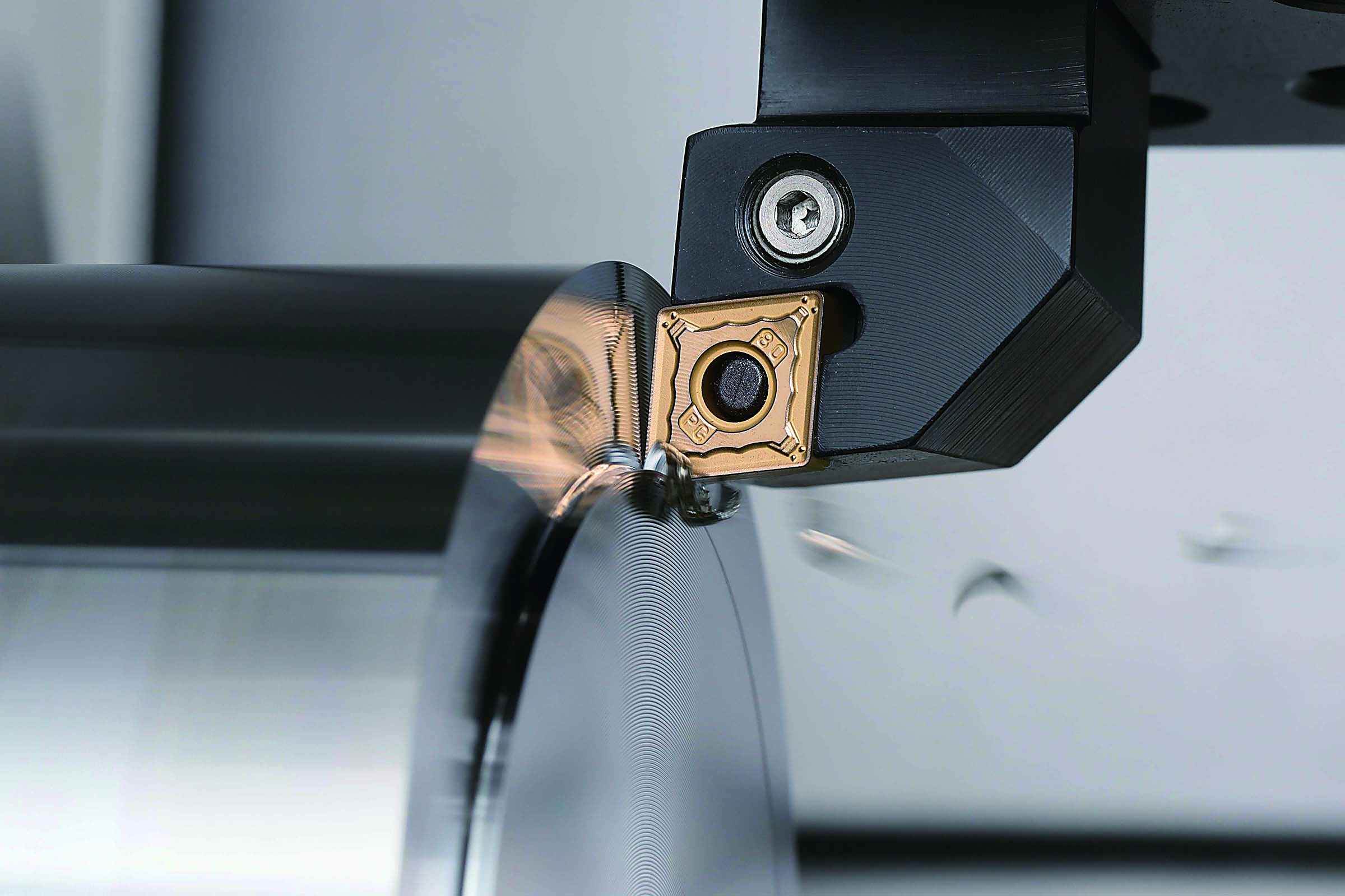
Turning operations, in which an insert continuously cuts a workpiece material, enable CVD coatings to shine. Czettl said CVD-coated inserts are still dominant in turning because they effectively resist abrasion and wear and have a high level of hot hardness to combat carbide’s worst enemy: high temperature.
He estimates that at least 60% of turning inserts are CVD-coated. Milling and grooving, however, involve interrupted cuts, and he said at least 60% of the tougher PVD-coated inserts are used for those applications.
Wilshire said the split is likely greater, with 70% to 75% of turning inserts being CVD-coated and only 10% of milling inserts being CVD-coated.
“For milling,” he said, “with the constant interruption, we have found — and everyone else has found as well — that PVD coatings for the most part are unrivaled in those applications.”
Drilling sometimes takes a hybrid approach. Wilshire explained that the outer insert can be a CVD-coated one to better resist wear at a high speed when drilling while the center pocket accepts a PVD-coated insert, which has a 0 sfm at the center, and the surface footage only increases away from the center.
“So you can increase the speeds, shorten cycle time and increase throughput,” he said about the combination of coatings.
The workpiece material also determines which type of coating to select. Evans said industries that machine a lot of carbon steel (ISO P and ISO K materials), such as automotive and heavy equipment, use a lot of CVD-coated inserts because of the heat protection they provide to the carbide substrate while resisting crater and flank wear. The coatings are effective even when cutting stainless steel (ISO M), he said.
In contrast, he said markets big on machining heat-resistant superalloys and titanium alloys (ISO S), such as aerospace, apply more PVD-coated inserts to better shear those challenging materials.
“Because of the temperature difference in the furnaces,” Evans said, “you can put a sharper edge on a PVD-coated insert.”
He said the aerospace industry also cuts a significant amount of composites and stacked materials, and the thinner PVD coating helps maintain a sharp edge to avoid fraying the workpiece. Uncoated inserts might be suitable as well, he said.
Wilshire added aluminum and plastics to the list of materials that can be cut effectively with highly polished, uncoated inserts.
Once a CVD coating is deposited on an insert, the product is not yet complete.
“Most of the CVD-coated inserts we offer have a post-coating process to smooth the coating, such as polishing and brushing,” Wilshire said.
Post-treatment also helps reduce stresses that can cause cracking as the coating shrinks more than the carbide during the CVD process, Czettl said. In addition, Ceratizit tries to convert the residual tensile stresses into a crack-resistant compressive stress, which is a topic of numerous peer-reviewed publications as well.
“We usually do that with a dry-blasting process,” he said, “which is better than wet-blasting processes.”
While PVD-coated inserts have an edge over CVD-coated ones when it comes to market share, that may not always be the case as toolmakers work on developing technologies to improve the performance of CVD coatings.
“In the future, I can see CVD becoming more dominant,” Evans said, “because there’s more technology that’s coming that will allow us to put sharper edges on CVD-coated inserts.”
For more information from Kyocera Precision Tools about its CVD-coated inserts, view a video presentation at cteplus.delivr.com/2bn2e
A High-Speed Finish
Carbide isn’t the only cutting tool substrate being CVD-coated. CVD-coated cermet inserts are also available, such as Kyocera Precision Tools Inc.’s most recent advancement: the CCX CVD-coated cermet insert for finishing. Technical Center Manager Brian Wilshire explained that the thermal expansion rates of the cermet and the CVD coating enable the coating to achieve a strong residual compressive stress that prevents cracks.
“We have a tougher cermet than the uncoated version because of the CVD coating,” he said.
Wilshire said end users typically are locked into a particular feed rate to maintain a specified surface roughness.
“Wiper inserts can be used for some of those applications,” he said, “but only if you are machining parallel or perpendicular to the centerline. Anything with profiling cuts or angled cuts, the wiper won’t really help.”
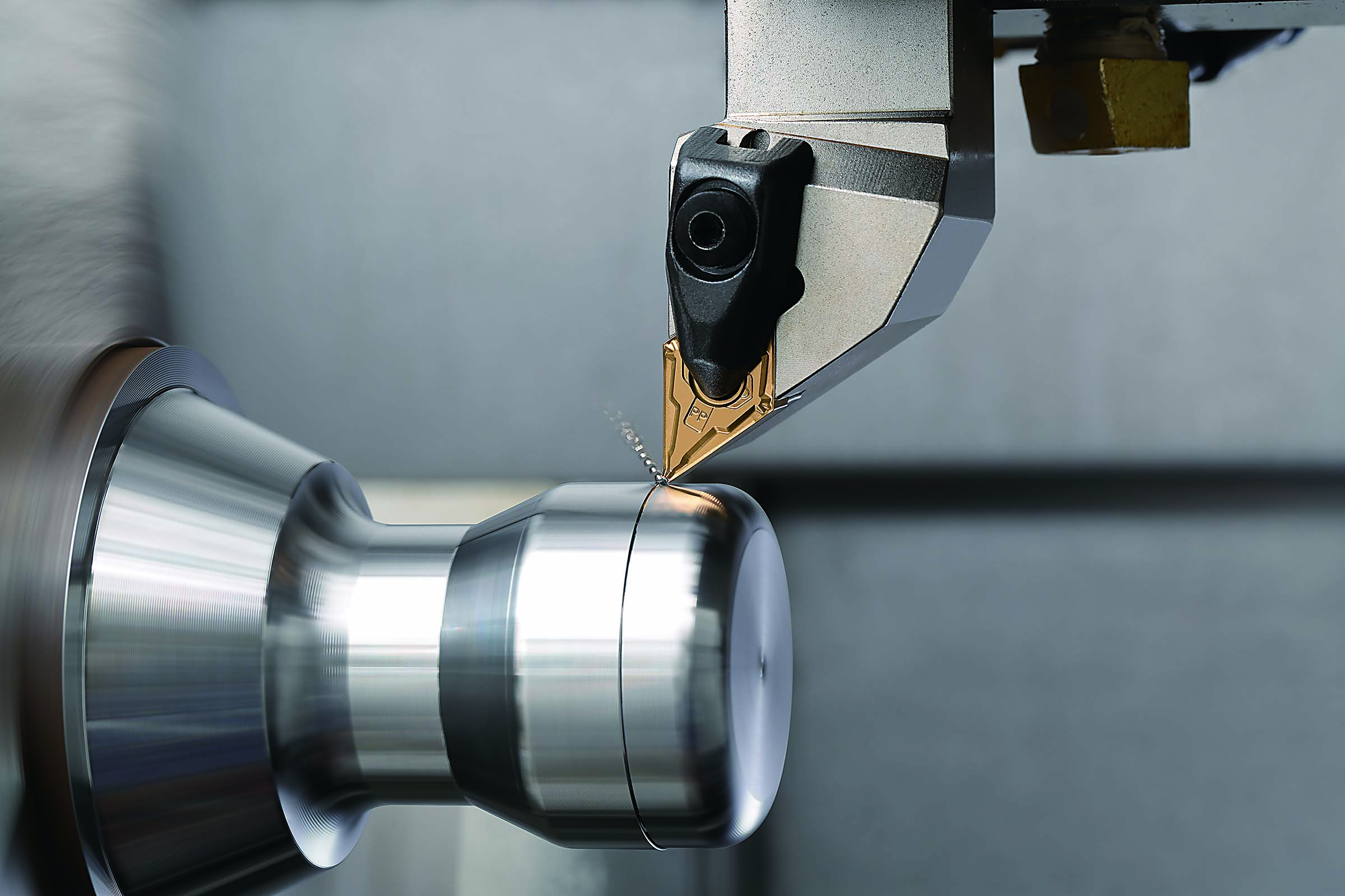
finishing of low-carbon steel, general steel and cast iron. Image courtesy of Kyocera Precision Tools
In those situations, Wilshire said the only way to shorten cycle time is to increase cutting speed, and the CVD-coated insert can run at a faster cutting speed than PVD-coated or uncoated cermet and impart the needed surface finish.
“In some cases,” he said, “in low-carbon steel we are able to run twice the cutting speed with CCX compared to our PVD-coated cermet.”
To effectively coat cermet via CVD, Wilshire said the toolmaker had to upgrade the substrate’s grain structure and minimize leaching of the binder.
“We went to a fine-grain cermet and refined the binder material so that it could accept a CVD coating,” he said.
While a small minority of the carbide inserts that the company sells are uncoated, Wilshire said about half of the cermet products don’t wear a coat.
“It’s a niche product,” he said about CCX, “but we’re seeing steady growth as people find out about it and see the benefit of shortening the finishing process.”
Contact Details

Contact Details
Contact Details
Related Glossary Terms
- alloys
alloys
Substances having metallic properties and being composed of two or more chemical elements of which at least one is a metal.
- aluminum oxide
aluminum oxide
Aluminum oxide, also known as corundum, is used in grinding wheels. The chemical formula is Al2O3. Aluminum oxide is the base for ceramics, which are used in cutting tools for high-speed machining with light chip removal. Aluminum oxide is widely used as coating material applied to carbide substrates by chemical vapor deposition. Coated carbide inserts with Al2O3 layers withstand high cutting speeds, as well as abrasive and crater wear.
- brushing
brushing
Generic term for a curve whose shape is controlled by a combination of its control points and knots (parameter values). The placement of the control points is controlled by an application-specific combination of order, tangency constraints and curvature requirements. See NURBS, nonuniform rational B-splines.
- chemical vapor deposition ( CVD)
chemical vapor deposition ( CVD)
High-temperature (1,000° C or higher), atmosphere-controlled process in which a chemical reaction is induced for the purpose of depositing a coating 2µm to 12µm thick on a tool’s surface. See coated tools; PVD, physical vapor deposition.
- chemical vapor deposition ( CVD)2
chemical vapor deposition ( CVD)
High-temperature (1,000° C or higher), atmosphere-controlled process in which a chemical reaction is induced for the purpose of depositing a coating 2µm to 12µm thick on a tool’s surface. See coated tools; PVD, physical vapor deposition.
- composites
composites
Materials composed of different elements, with one element normally embedded in another, held together by a compatible binder.
- cutting speed
cutting speed
Tangential velocity on the surface of the tool or workpiece at the cutting interface. The formula for cutting speed (sfm) is tool diameter 5 0.26 5 spindle speed (rpm). The formula for feed per tooth (fpt) is table feed (ipm)/number of flutes/spindle speed (rpm). The formula for spindle speed (rpm) is cutting speed (sfm) 5 3.82/tool diameter. The formula for table feed (ipm) is feed per tooth (ftp) 5 number of tool flutes 5 spindle speed (rpm).
- feed
feed
Rate of change of position of the tool as a whole, relative to the workpiece while cutting.
- flank wear
flank wear
Reduction in clearance on the tool’s flank caused by contact with the workpiece. Ultimately causes tool failure.
- gang cutting ( milling)
gang cutting ( milling)
Machining with several cutters mounted on a single arbor, generally for simultaneous cutting.
- grooving
grooving
Machining grooves and shallow channels. Example: grooving ball-bearing raceways. Typically performed by tools that are capable of light cuts at high feed rates. Imparts high-quality finish.
- hardness
hardness
Hardness is a measure of the resistance of a material to surface indentation or abrasion. There is no absolute scale for hardness. In order to express hardness quantitatively, each type of test has its own scale, which defines hardness. Indentation hardness obtained through static methods is measured by Brinell, Rockwell, Vickers and Knoop tests. Hardness without indentation is measured by a dynamic method, known as the Scleroscope test.
- milling
milling
Machining operation in which metal or other material is removed by applying power to a rotating cutter. In vertical milling, the cutting tool is mounted vertically on the spindle. In horizontal milling, the cutting tool is mounted horizontally, either directly on the spindle or on an arbor. Horizontal milling is further broken down into conventional milling, where the cutter rotates opposite the direction of feed, or “up” into the workpiece; and climb milling, where the cutter rotates in the direction of feed, or “down” into the workpiece. Milling operations include plane or surface milling, endmilling, facemilling, angle milling, form milling and profiling.
- parallel
parallel
Strip or block of precision-ground stock used to elevate a workpiece, while keeping it parallel to the worktable, to prevent cutter/table contact.
- physical vapor deposition ( PVD)
physical vapor deposition ( PVD)
Tool-coating process performed at low temperature (500° C), compared to chemical vapor deposition (1,000° C). Employs electric field to generate necessary heat for depositing coating on a tool’s surface. See CVD, chemical vapor deposition.
- physical vapor deposition ( PVD)2
physical vapor deposition ( PVD)
Tool-coating process performed at low temperature (500° C), compared to chemical vapor deposition (1,000° C). Employs electric field to generate necessary heat for depositing coating on a tool’s surface. See CVD, chemical vapor deposition.
- polishing
polishing
Abrasive process that improves surface finish and blends contours. Abrasive particles attached to a flexible backing abrade the workpiece.
- profiling
profiling
Machining vertical edges of workpieces having irregular contours; normally performed with an endmill in a vertical spindle on a milling machine or with a profiler, following a pattern. See mill, milling machine.
- superalloys
superalloys
Tough, difficult-to-machine alloys; includes Hastelloy, Inconel and Monel. Many are nickel-base metals.
- titanium aluminum nitride ( TiAlN)
titanium aluminum nitride ( TiAlN)
Often used as a tool coating. AlTiN indicates the aluminum content is greater than the titanium. See coated tools.
- titanium carbide ( TiC)
titanium carbide ( TiC)
Extremely hard material added to tungsten carbide to reduce cratering and built-up edge. Also used as a tool coating. See coated tools.
- titanium carbonitride ( TiCN)
titanium carbonitride ( TiCN)
Often used as a tool coating. See coated tools.
- titanium nitride ( TiN)
titanium nitride ( TiN)
Added to titanium-carbide tooling to permit machining of hard metals at high speeds. Also used as a tool coating. See coated tools.
- turning
turning
Workpiece is held in a chuck, mounted on a face plate or secured between centers and rotated while a cutting tool, normally a single-point tool, is fed into it along its periphery or across its end or face. Takes the form of straight turning (cutting along the periphery of the workpiece); taper turning (creating a taper); step turning (turning different-size diameters on the same work); chamfering (beveling an edge or shoulder); facing (cutting on an end); turning threads (usually external but can be internal); roughing (high-volume metal removal); and finishing (final light cuts). Performed on lathes, turning centers, chucking machines, automatic screw machines and similar machines.
- wear resistance
wear resistance
Ability of the tool to withstand stresses that cause it to wear during cutting; an attribute linked to alloy composition, base material, thermal conditions, type of tooling and operation and other variables.
- wiper
wiper
Metal-removing edge on the face of a cutter that travels in a plane perpendicular to the axis. It is the edge that sweeps the machined surface. The flat should be as wide as the feed per revolution of the cutter. This allows any given insert to wipe the entire workpiece surface and impart a fine surface finish at a high feed rate.
Author

Alan holds a bachelor’s degree in journalism from Southern Illinois University Carbondale. Including his 20 years at CTE, Alan has more than 30 years of trade journalism experience.
Contributors
Ceratizit USA Inc.
800-783-2280
www.ceratizit.com
Kyocera Precision Tools Inc.
800-823-7284
www.kyoceraprecisiontools.com
Sandvik Coromant Co.
800-726-3845
www.sandvik.coromant.com
