Generating spherical surfaces: General Industry Coverage
A unique manual milling method is available for generating geometrically true spherical surfaces. This technique can be used to machine convex and concave spherical surfaces. Other than the milling machine, the only tools needed are a boring head and a rotary table.
A unique manual milling method is available for generating geometrically true spherical surfaces. This technique can be used to machine convex and concave spherical surfaces. Other than the milling machine, the only tools needed are a boring head and a rotary table.
If you have a CNC lathe or mill, this is really just an academic exercise. The technique is interesting in that it is self-correcting and self-proving, which is not true of CNC equipment. If you don’t have any CNC machines, you can add a neat trick to your toolbox.
I learned this technique years ago from my old toolmaker friend Charlie. When he first told me about it, I was skeptical until I tried it. If you have a computer drafting program, you can make short work of the math and setup angle. This method is far superior for forming tools and beats the pants off swinging arc fixtures because the spherical surface is a true geometric generation. The spherical form is limited only by the accuracy of the machine spindle and the rotary table—two intersecting circular paths that produce a true spherical surface.
Courtesy of All images: T. Lipton
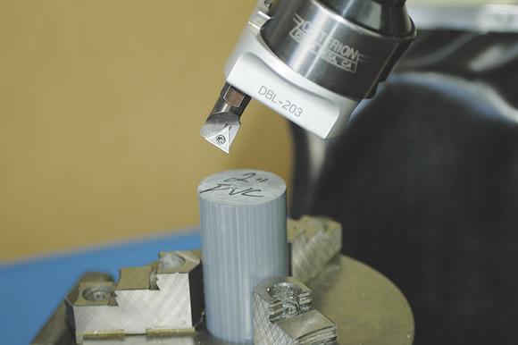
When working with a convex surface, the cutting edge faces inward.
Imagine a cutting tool that only cuts a hollow circle, kind of like a hole saw. When the tool is set at an angle other than the axis of the rotary table and the part is rotated under the tool, a spherical surface is generated.
The boring head is tipped at an angle that represents the chord of the desired spherical segment. A single-point cutting tool is applied and, depending on whether the form is concave or convex, the cutting edge is reversed. For convex surfaces, the cutting edge faces inward. For concave surfaces, the cutting edge faces outward, as it would in normal boring head work.
As the tool is advanced into the workpiece, the rotary table is rotated through 360°. The rotary table is also fed into the tool along the X-axis.
When you first try this method, use plastic so you can quickly see exactly what is happening before you try it on important parts. There are three variables you must understand to get controllable results. The first involves basic calculations. The second is the setup and the third is the execution—actually doing it.
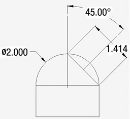
A graphical setup for cutting a full hemisphere 2 ” in diameter.
Review the print ads from this magazine to continue
This quick advertiser review unlocks the rest of the article and keeps the full-screen reader focused on the ads instead of the page chrome.


MFGAxis Discussion