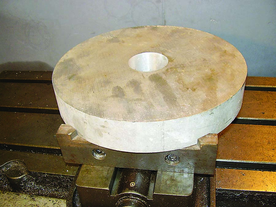
Here we have a 279.4 mm (11") dia. × 50.8 mm (2") thick piece of billet aluminum that needs 0.0018 m3 (110 in.3) of material removed by milling. In this column, I’ll show how to use a milling vise for easily made, trouble-free fixturing. In my next column, I’ll go through horsepower and metal removal calculation.
The vise is a standard 152.4 mm (6") and has the popular wedge clamping mechanism. These vises are easy to use, develop good clamping force and give good, repeatable positioning of a workpiece. A variety of replacement jaws are available for clamping a round workpiece, but they’re not good for this application.
To hold this part, a pair of vise jaws are made from 1018 cold-rolled steel. The front jaw is made from 25.4 mm (1") × 57.15 mm (2.25") stock, and the back jaw is made from 19.05 mm (0.75") × 57.15 mm stock. The front jaw mounts in the normal way while the back jaw mounts to the back of the vise’s slide block. The first photograph shows the jaws mounted to the vise. Note the 12.7 mm (0.5") dia. hole drilled into the top right center of the front jaw. The hole is for indexing the setup. When designing a set of jaws, I like to put in this feature. It’s a timesaver when setting up a job. Aggressive metal removal is in order, so care needs to be taken in designing the surfaces that clamp the part.
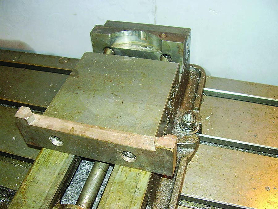
When designing the jaws, it’s important to take into consideration the mechanical properties of the jaw material and the workpiece. This workpiece is 6061-T6 aluminum. Yield strength of the materials and the coefficient of friction between the materials should be considered. For some parts, it’s
critical that the jaws don’t deform the material when clamping. That’s the case here. I don’t want jaw marks on the part. And of course, the jaws should not be bent. This means that the clamping force stresses must be well below the yield strength.
- The yield strength of 1018 cold-rolled steel is 30,000 psi.
- The yield strength of 6061-T6 aluminum is 40,000 psi.
- The coefficient of static friction between clean 1018 and 6061 is 0.6.
- This vise will develop 2,722 kg (6,000 lbs.) of clamping force when the vise’s lead screw is tightened to 80 ft.-lbs.
The faces that contact the workpiece have a 279.4 mm dia. arc to match the workpiece outer diameter. The contact surfaces are 10.16 mm (0.4") high. The front jaw contact surface is 76.2 mm (3") long, and the back jaw has two contact surfaces that are each 15.24 mm (0.6") long. There is a 60-degree angle between the two back clamping surfaces and the center of the part.
The stress is more in the back jaw clamping surfaces because of the smaller clamping area and angle. A little math shows that stress in the back jaw clamping surfaces is 14,000 psi, which gives good safety allowance. The coefficient of friction says that when clamped with 2,722 kg of force (6,000 lbs. against the front jaw balanced by 6,000 lbs. against the back jaw), 1,633 kg (3,600 lbs.) of force resist pulling the part vertically in the front jaw. It’s more in the back jaw because of the clamping angle. The second photo on Page 11 shows the setup ready for work.
So how much metal can be removed per minute? Formulas for power consumption when milling are in Machinery’s Handbook and on the internet. From these, you can develop force vectors, which tell how aggressive the milling can be without pulling the part out of the vise.
I’ll go through that stuff in my next column.
Related Glossary Terms
- gang cutting ( milling)
gang cutting ( milling)
Machining with several cutters mounted on a single arbor, generally for simultaneous cutting.
- mechanical properties
mechanical properties
Properties of a material that reveal its elastic and inelastic behavior when force is applied, thereby indicating its suitability for mechanical applications; for example, modulus of elasticity, tensile strength, elongation, hardness and fatigue limit.
- milling
milling
Machining operation in which metal or other material is removed by applying power to a rotating cutter. In vertical milling, the cutting tool is mounted vertically on the spindle. In horizontal milling, the cutting tool is mounted horizontally, either directly on the spindle or on an arbor. Horizontal milling is further broken down into conventional milling, where the cutter rotates opposite the direction of feed, or “up” into the workpiece; and climb milling, where the cutter rotates in the direction of feed, or “down” into the workpiece. Milling operations include plane or surface milling, endmilling, facemilling, angle milling, form milling and profiling.
- outer diameter ( OD)
outer diameter ( OD)
Dimension that defines the exterior diameter of a cylindrical or round part. See ID, inner diameter.
- yield strength
yield strength
Stress at which a material exhibits a specified deviation from proportionality of stress and strain. An offset of 0.2 percent is used for many metals. Compare with tensile strength.
Author

Brandt Taylor is owner of Berlin, Massachusetts-based Taylor Engineering, a machine shop.