Recent studies provide clues to the mechanisms behind the success of metal-ion implantation.
In spite of past studies showing that ion implantation can improve the performance of cutting tools, the process is not widely accepted by the metalworking community. Researchers are still debating how ion implantation works, and users are reluctant to embrace a technology that is not well understood. Memories of the high investment cost of earlier systems also continue to discourage users, who still believe it costs between $1 and $10 to treat a square centimeter of tool surface.
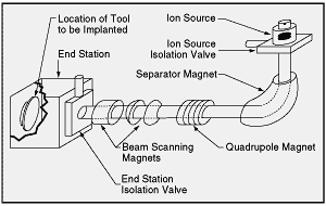 Figure 1: In a beam-line ion-implantation system, a large separator magnet is needed to separate the metal ions from other ions produced by the source. Additional components are needed for beam focusing and steering. |
|
The newer ion-implantation systems using metal vapor vacuum arc (MEVVA) ion sources are much more economical. They can treat inserts for $0.05 to $0.50 per square centimeter, depending on the implantation equipment’s capacity and the number of parts involved. With the price of ion implantation falling, machinists might be encouraged to use the technology if they can be shown how implantation can enhance their tools’ endurance. In recent years, researchers have conducted a number of tests that not only prove that ion implantation is effective, but also provide insights into the structural mechanisms at work.
Like other ion-implantation methods, the MEVVA system bombards the tool’s surface with accelerated metal ions. While ions penetrate the surface to a depth of about 0.1µm, they cause structural changes in the tool material that enhance its performance to a depth of several microns. Beam-line systems produce these ions from metal chlorides in the vapor phase. To create a usable beam, the metal ions must be magnetically separated from the mixture of metal and chlorine ions being created (Figure 1). The narrow beam exiting the separator must be scanned across the tool surface.
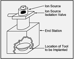 Figure 2: In a direct ion-implantation system with cathodic arc ion sources, only the desired metal ions are produced. |
|
With the MEVVA system, only a broad beam of metal ions is created, eliminating the need for a mass separator or beam scanner (Figure 2). Without these components, the implantation system is much less costly to build and operate.
The plasma in a MEVVA ion source is generated by a cathodic or vacuum arc. The arc produces a cathode spot on the surface of the ion-forming metal that is no more than 1µm in diameter. In this spot, current densities are so high that the metal ions produced are multiply charged. These ions, with their high energy level, are more effective than ions produced by arcs that form larger spots on the metal, because they cause greater work hardening when they strike the tool material.
Carbide Improvements
One series of tests shows how ion implantation using the MEVVA process can improve indexable solid-carbide tools. In these tests, titanium and nickel ions were implanted into various styles of carbide inserts and endmills. In the laboratory, the tools were used to turn steel stock. In the field, implanted tools were used to turn, mill, thread, drill, and groove various steels and titanium and aluminum alloys under commercial conditions. In some field applications, increased speeds and feeds were used.
The industrial-standard cemented-carbide indexable inserts implanted with ions in the laboratory phase of this study were coated with Al2O3. The triangular shape of the inserts had an inscribed circle of 0.375" and a tip radius of 0.015". Before implantation, the inserts were cleaned in ultrasonic baths of acetone and methyl alcohol and then dried. No other preparation was necessary. During implantation, the carbide inserts’ temperature remained below 150°C.
The treated inserts were tested in a turning application by Circle Machine Co., Monrovia, CA. A speed of 700 sfm, a feed rate of 0.007 ipr, and a DOC of 0.010" were used to cut 4140 steel. A TiN-coated insert also was tested, but because it would not cut at the DOC used by the other inserts, a DOC of 0.005" was used.
As recorded in Table 1, the implanted insert cut 70% more parts than the unimplanted insert when an oil coolant was used. Neither insert performed as well without coolant, and there was no difference in the number of parts they could cut. The unimplanted TiN-coated insert produced the fewest number of parts of any insert tested.
|
|||||||||||||||||||||||||||||||||||
| Table 1: Results of turning tests using implanted and unimplanted carbide inserts. |
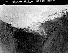 Figure 3a: An implanted insert that has failed because of cratering and chipping after turning 4140 steel with coolant. |
|
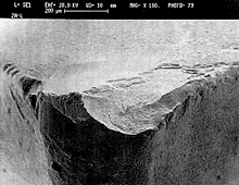 Figure 3b: An unimplanted insert showing a greater degree of chipping after turning 4140 steel with coolant. |
|
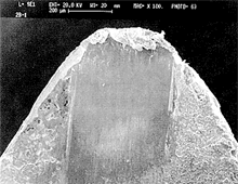 Figure 3c: An implanted insert that has failed because of BUE after turning 4140 steel without coolant. |
|
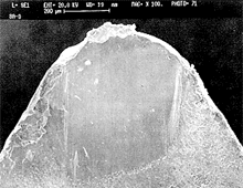 Figure 3d: An unimplanted insert run dry that has failed because of BUE after turning 4140 steel. |
|
The test inserts’ modes of failure were studied by scanning electron microscopy (SEM). Images of inserts after testing are shown in Figures 3a through 3d. Crater wear can be seen on the inserts depicted in 3a and 3b, which were tested with oil coolant. The chipping that caused both inserts to fail can be seen as well. As is apparent in the micrographs, the problem was more extensive in the unimplanted insert (3b). No fatigue cracking was observed in either sample, indicating that thermal fatigue was not a factor.
The SEM study also revealed why the inserts run without coolant failed significantly sooner than the samples with coolant. Wear was not the cause of failure in these cases. Both the implanted (3c) and unimplanted (3d) inserts failed because of BUE on the rake surface of the cutting tip. The problem began affecting the performance of the inserts well before they began to wear extensively. The fact that the implanted and unimplanted inserts produced the same number of parts suggests that ion implantation had no effect on the formation of BUE in these cases.
Elemental analysis of the worn surfaces of the inserts run with coolant was conducted by energy-dispersive analysis of X-rays during the SEM testing.
No aluminum was found in the chipped areas or in the craters on either insert run with coolant. This finding indicates that the Al2O3 was largely removed from the cutting surfaces long before failure. Where the aluminum was detected in the crater areas, neither the titanium nor the nickel from the implantation process was observed, indicating that the implanted surface layer had been removed.
In the Field
Inserts implanted using the same process researchers used for the laboratory inserts were tested extensively in commercial applications by shops in Southern California. Both TiN-coated and uncoated inserts were tested. Users installed implanted versions of the inserts they were using when it was time to change cutting tools. Typical results reported by the users are recorded in Table 2.
|
||||||||||||||||||||||||||||||||||||||||
| Table 2: Typical improvements seen by users testing implanted inserts in commercial applications. |
As the data in Table 2 reveals, most users saw an improvement in performance when they switched to implanted inserts. These improvements included more parts cut per insert, higher speeds and feeds, better surface finishes, and a less frequent need to adjust tool offsets.
The ion implantation did not always produce an improvement in insert performance. However, in over 75% of the 25 individual test series studied, the implanted tool inserts lasted more than twice as long as the unimplanted inserts. In some cases, implanted inserts running at higher speeds or feeds outperformed unimplanted inserts cutting at normal rates. Users also found that coated inserts were slightly more likely to benefit from implantation than uncoated inserts. The implantation process improved the coating and slowed the rate at which it wore off the tools. Of the eight series of coated-insert tests conducted, 88% showed improvements when unimplanted inserts were replaced with implanted versions. In the 17 series of tests on uncoated inserts, 71% showed an improvement after switching.
The analysis of failure modes indicates that, in these particular cases, ion implantation reduced the rate of wear without affecting the mode of failure. Implantation seemed to reduce the amount of chipping at failure; however, where failure was due to BUE, implantation was of little benefit.
Why Does It Work?
The implanted depth of the metal ions is only 0.02µm to 0.20µm, and this layer is too shallow to produce the observed effects on its own. As was seen in the lab-tested inserts, implanted inserts continue to perform well even after the implanted layer has worn off. Two theories have evolved to explain how ion implantation improves tool performance even when the implanted layer is gone. One theory suggests that implantation produces compression stress in the material. In the plane of the tool’s surface, this stress closes up any pre-existing cracks and prevents new ones from forming. When inserts chip, the problem often occurs at the lips of cracks. With the cracks eliminated, this source of chipping is no longer a threat.
However, recent studies indicate that ion implantation does not increase the compressive stress of the substrate in every case. In other tests, where a 10kV high-voltage pulsed bias was applied to a substrate during a coating process, a dramatic reduction in residual compressive stress was seen. Because the bias’ effects on metal are similar to ion implantation’s, the implication is that the stresses induced would also be similar.
A second theory suggests that ion implantation induces or otherwise causes the formation of a dislocation network structure in the material, and it is this structure that suppresses both crack formation and crack propagation (Figure 4). A number of studies support this theory.
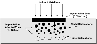 Figure 4: Ion implantation produces an implanted zone, where the ions settle, and an implantation-affected zone, where the mechanical effects of ion bombardment cause changes in the material’s morphology, stress, and chemistry. |
In one study, researchers measured dislocation densities following metal ion implantation and found these to be much greater than densities seen in unimplanted materials. Structural changes extended 20µm below the surface, and evidence of changes in dislocation density was found down to 100µm or more.
Others have reported modifications to many physical properties brought on by the dislocation structure after ion implantation, including changes in the material’s hardness, wear resistance, and phase structure. It is believed that the higher hardness (which is proportional to the dislocation density) leads to higher abrasive wear resistance and that any increase in compressive stress that may result from ion implantation increases the fatigue-wear resistance.
Using the second theory to explain the results observed in the laboratory with the Al2O3-coated inserts, it might be said that the ion implantation caused a change in the dislocation structure of the coating and, possibly, in the carbide substrate as well. This led to increased wear resistance and, thus, to the observed improvements in tool life.
It is worth adding that failures due to such mechanisms as BUE would not be affected by this increased wear resistance. This explains why, when the inserts were run in the lab without coolant, there was no difference in the performance of the implanted and unimplanted inserts. With a coolant, insert failure is due to abrasive wear followed by chip-out failure. These are failure modes that are affected by increases in wear resistance. When coolant is not used, the insert fails because material adheres to the insert, a problem that is not solved by an increase in wear resistance.
It may be possible, however, to reduce BUE by employing a different energy and dose of implantation metal during the process. In other studies, researchers have observed a reduction in the friction coefficient after ion implantation. If this effect can be reproduced by altering the implantation process, it might prevent the buildup of material on the insert’s edge.
The data from laboratory and field tests that are presented here indicate that ion implantation can markedly increase the life of coated and uncoated carbide cutting tools by as much as 4.8 times. Now that modern processes have brought the cost of ion implantation down, the technology offers an inexpensive way to improve tool performance. As understanding of the mechanics behind the process grows, it should be possible to modify the parameters of implantation to ensure success in a variety of applications.
About the Authors
James Treglio is president and CEO, Anthony Perry is director of research and technology, and Albert Tian is senior engineer for ISM Technologies Inc., San Diego.
Related Glossary Terms
- abrasive
abrasive
Substance used for grinding, honing, lapping, superfinishing and polishing. Examples include garnet, emery, corundum, silicon carbide, cubic boron nitride and diamond in various grit sizes.
- alloys
alloys
Substances having metallic properties and being composed of two or more chemical elements of which at least one is a metal.
- aluminum alloys
aluminum alloys
Aluminum containing specified quantities of alloying elements added to obtain the necessary mechanical and physical properties. Aluminum alloys are divided into two categories: wrought compositions and casting compositions. Some compositions may contain up to 10 alloying elements, but only one or two are the main alloying elements, such as copper, manganese, silicon, magnesium, zinc or tin.
- built-up edge ( BUE)
built-up edge ( BUE)
1. Permanently damaging a metal by heating to cause either incipient melting or intergranular oxidation. 2. In grinding, getting the workpiece hot enough to cause discoloration or to change the microstructure by tempering or hardening.
- coolant
coolant
Fluid that reduces temperature buildup at the tool/workpiece interface during machining. Normally takes the form of a liquid such as soluble or chemical mixtures (semisynthetic, synthetic) but can be pressurized air or other gas. Because of water’s ability to absorb great quantities of heat, it is widely used as a coolant and vehicle for various cutting compounds, with the water-to-compound ratio varying with the machining task. See cutting fluid; semisynthetic cutting fluid; soluble-oil cutting fluid; synthetic cutting fluid.
- cratering
cratering
Depressions formed on the face of a cutting tool caused by heat, pressure and the motion of chips moving across the tool’s surface.
- endmill
endmill
Milling cutter held by its shank that cuts on its periphery and, if so configured, on its free end. Takes a variety of shapes (single- and double-end, roughing, ballnose and cup-end) and sizes (stub, medium, long and extra-long). Also comes with differing numbers of flutes.
- fatigue
fatigue
Phenomenon leading to fracture under repeated or fluctuating stresses having a maximum value less than the tensile strength of the material. Fatigue fractures are progressive, beginning as minute cracks that grow under the action of the fluctuating stress.
- feed
feed
Rate of change of position of the tool as a whole, relative to the workpiece while cutting.
- gang cutting ( milling)
gang cutting ( milling)
Machining with several cutters mounted on a single arbor, generally for simultaneous cutting.
- grooving
grooving
Machining grooves and shallow channels. Example: grooving ball-bearing raceways. Typically performed by tools that are capable of light cuts at high feed rates. Imparts high-quality finish.
- hardening
hardening
Process of increasing the surface hardness of a part. It is accomplished by heating a piece of steel to a temperature within or above its critical range and then cooling (or quenching) it rapidly. In any heat-treatment operation, the rate of heating is important. Heat flows from the exterior to the interior of steel at a definite rate. If the steel is heated too quickly, the outside becomes hotter than the inside and the desired uniform structure cannot be obtained. If a piece is irregular in shape, a slow heating rate is essential to prevent warping and cracking. The heavier the section, the longer the heating time must be to achieve uniform results. Even after the correct temperature has been reached, the piece should be held at the temperature for a sufficient period of time to permit its thickest section to attain a uniform temperature. See workhardening.
- hardness
hardness
Hardness is a measure of the resistance of a material to surface indentation or abrasion. There is no absolute scale for hardness. In order to express hardness quantitatively, each type of test has its own scale, which defines hardness. Indentation hardness obtained through static methods is measured by Brinell, Rockwell, Vickers and Knoop tests. Hardness without indentation is measured by a dynamic method, known as the Scleroscope test.
- inscribed circle ( IC)
inscribed circle ( IC)
Imaginary circle that touches all sides of an insert. Used to establish size. Measurements are in fractions of an inch and describe the diameter of the circle.
- metalworking
metalworking
Any manufacturing process in which metal is processed or machined such that the workpiece is given a new shape. Broadly defined, the term includes processes such as design and layout, heat-treating, material handling and inspection.
- milling
milling
Machining operation in which metal or other material is removed by applying power to a rotating cutter. In vertical milling, the cutting tool is mounted vertically on the spindle. In horizontal milling, the cutting tool is mounted horizontally, either directly on the spindle or on an arbor. Horizontal milling is further broken down into conventional milling, where the cutter rotates opposite the direction of feed, or “up” into the workpiece; and climb milling, where the cutter rotates in the direction of feed, or “down” into the workpiece. Milling operations include plane or surface milling, endmilling, facemilling, angle milling, form milling and profiling.
- milling machine ( mill)
milling machine ( mill)
Runs endmills and arbor-mounted milling cutters. Features include a head with a spindle that drives the cutters; a column, knee and table that provide motion in the three Cartesian axes; and a base that supports the components and houses the cutting-fluid pump and reservoir. The work is mounted on the table and fed into the rotating cutter or endmill to accomplish the milling steps; vertical milling machines also feed endmills into the work by means of a spindle-mounted quill. Models range from small manual machines to big bed-type and duplex mills. All take one of three basic forms: vertical, horizontal or convertible horizontal/vertical. Vertical machines may be knee-type (the table is mounted on a knee that can be elevated) or bed-type (the table is securely supported and only moves horizontally). In general, horizontal machines are bigger and more powerful, while vertical machines are lighter but more versatile and easier to set up and operate.
- rake
rake
Angle of inclination between the face of the cutting tool and the workpiece. If the face of the tool lies in a plane through the axis of the workpiece, the tool is said to have a neutral, or zero, rake. If the inclination of the tool face makes the cutting edge more acute than when the rake angle is zero, the rake is positive. If the inclination of the tool face makes the cutting edge less acute or more blunt than when the rake angle is zero, the rake is negative.
- sawing machine ( saw)
sawing machine ( saw)
Machine designed to use a serrated-tooth blade to cut metal or other material. Comes in a wide variety of styles but takes one of four basic forms: hacksaw (a simple, rugged machine that uses a reciprocating motion to part metal or other material); cold or circular saw (powers a circular blade that cuts structural materials); bandsaw (runs an endless band; the two basic types are cutoff and contour band machines, which cut intricate contours and shapes); and abrasive cutoff saw (similar in appearance to the cold saw, but uses an abrasive disc that rotates at high speeds rather than a blade with serrated teeth).
- threading
threading
Process of both external (e.g., thread milling) and internal (e.g., tapping, thread milling) cutting, turning and rolling of threads into particular material. Standardized specifications are available to determine the desired results of the threading process. Numerous thread-series designations are written for specific applications. Threading often is performed on a lathe. Specifications such as thread height are critical in determining the strength of the threads. The material used is taken into consideration in determining the expected results of any particular application for that threaded piece. In external threading, a calculated depth is required as well as a particular angle to the cut. To perform internal threading, the exact diameter to bore the hole is critical before threading. The threads are distinguished from one another by the amount of tolerance and/or allowance that is specified. See turning.
- titanium nitride ( TiN)
titanium nitride ( TiN)
Added to titanium-carbide tooling to permit machining of hard metals at high speeds. Also used as a tool coating. See coated tools.
- turning
turning
Workpiece is held in a chuck, mounted on a face plate or secured between centers and rotated while a cutting tool, normally a single-point tool, is fed into it along its periphery or across its end or face. Takes the form of straight turning (cutting along the periphery of the workpiece); taper turning (creating a taper); step turning (turning different-size diameters on the same work); chamfering (beveling an edge or shoulder); facing (cutting on an end); turning threads (usually external but can be internal); roughing (high-volume metal removal); and finishing (final light cuts). Performed on lathes, turning centers, chucking machines, automatic screw machines and similar machines.
- wear resistance
wear resistance
Ability of the tool to withstand stresses that cause it to wear during cutting; an attribute linked to alloy composition, base material, thermal conditions, type of tooling and operation and other variables.
