Extended-reach toolholders remain a requirement
Multiple-axis machines increase workpiece accessibility but some jobs still require these specialized toolholders.
Because of interference, such as from a machine spindle snout, getting into certain features on a vertical machining center sometimes requires toolholders with long gauge lengths, said Jack Burley, vice president of sales and engineering at BIG KAISER Precision Tooling Inc., Hoffman Estates, Illinois. The minimum Z-axis, which is the closest distance a spindle can be to the worktable, has to be made up by the length of the toolholder. In the case of a horizontal machining center, the shortest distance a spindle can be to the center of the table is also a dead zone that has to be made up by the toolholder, he said.
“At least 90% of the time, catalog toolholders typically in the range of 2″ to 6″ or 8″ are more than long enough to overcome these minimum strokes, dead zones or any other problems with machine limits,” Burley said. “It gets down to 10% of the problems—where either the parts are just so small or so close to the table or it’s on a horizontal where you have to reach across to the opposite side because of the feature that you’re trying to get to—where you need extended-reach toolholders.”
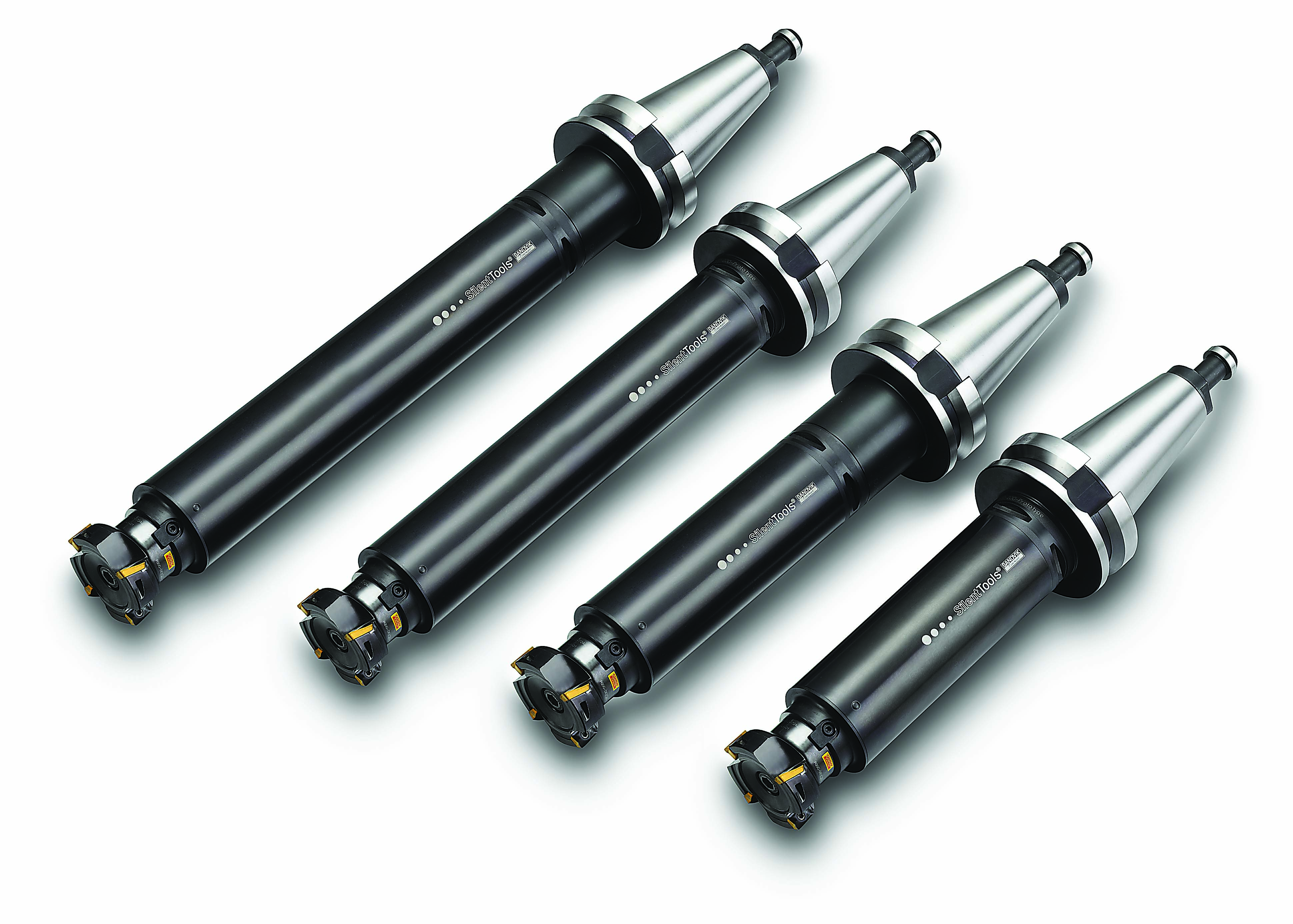
Sandvik Coromant’s Coromant Capto is available in various length extensions to optimize applications and with dampened extensions to minimize vibration. Image courtesy of Sandvik Coromant
All the recent investment in multiple-axis machines, with their increased accessibility to workpieces, has made many people believe that the need for extended-reach toolholders is greatly reduced if not eliminated.
“With the 5-axis, I can tilt things around to get into those places using a standard toolholder, but you’re always working off the center of the table,” Burley said. “So everywhere around it, there are going to be certain tilts that make it difficult to reach, like the B-axis all the way at 90° to the spindle, and some features down by the table itself.”
For situations like those, he thinks that extended-length toolholders always will be needed.
Optimal Length
CAM software tells a programmer the maximum and minimum gauge length from the spindle to the tip of the tool, Burley said. To determine other toolholder dimensions, a program’s collision detection system would calculate the maximum outside diameter of the toolholder and the optimum lengths to reach the longest conditions.
But what exactly makes a toolholder qualify as extended reach?
“Extended reach is not just how long it is but how long it is in relation to the tool diameter,” said Gregg Bishop, general manager of Ultra-Dex USA, Flushing, Michigan.
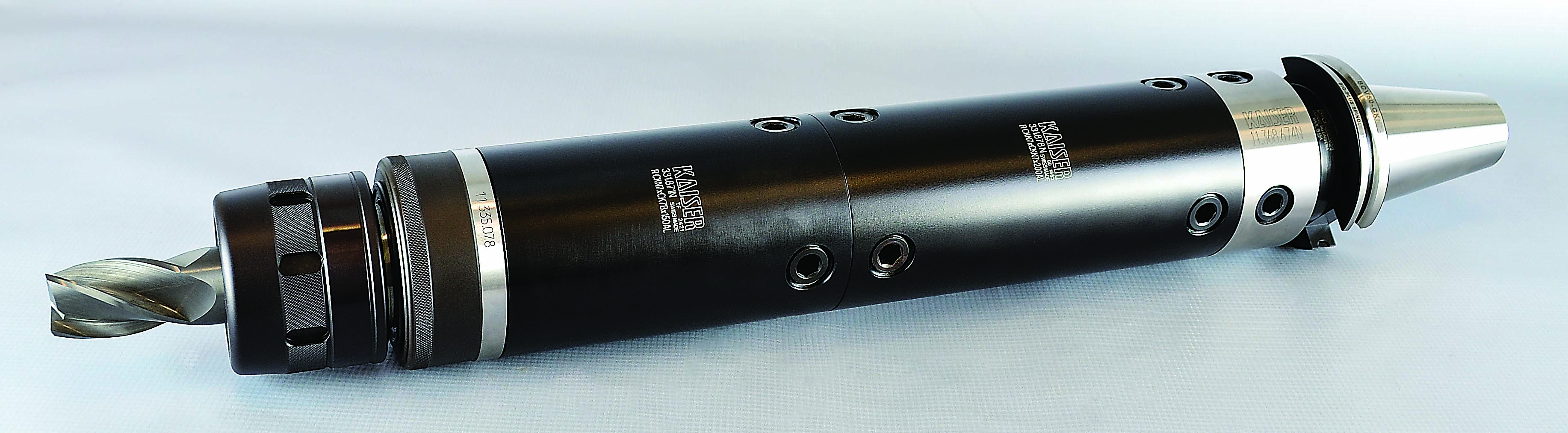
This modular toolholder system for larger, heavier tools includes a lightweight aluminum insert for extended-length toolholders. Image courtesy of BIG KAISER Precision Tooling
He considers extended reach to be any toolholder longer than five to seven times the diameter.
“It’s important that we keep those two things related,” he said. “So if we’re talking about 14″ of reach and the tool diameter is only ½”, we have a ratio of 28 times the diameter. But a 2″-dia. tool at 14″ length is only a 7-1 ratio, which is not particularly extended length.”
Extended-Reach Machining
Bishop said customers typically use extended-length holders to reach past fixtures, obstructions or part features to machine other part features beyond. For those applications, he recommends keeping cutting forces light to minimize radial or axial radial deflection.
“The cutting tool chosen could be more positive or high shearing,” he said. “Or we can apply toolpaths, such as high-efficiency or high-feed milling, which are different approaches to speeds and feeds and depth of cut.”
Trochoidal milling, a form of high-efficiency milling, is one option for extended-length toolholders because it exerts less stress on the spindle.
“The idea for a 1″-wide slot is to use a smaller-diameter cutting tool, like a ½” milling cutter instead of a 1″ cutter, and then feed the cutter forward in a circular toolpath opening the slot to the 1″ width instead of creating it with one big hog pass that’s 1″ wide,” said Mark Backus, product specialist for machine integration and tooling systems at Sandvik Coromant Co., Fair Lawn, New Jersey.
The main challenge with extended-reach toolholders is achieving suitable rigidity. The longer and thinner the holder, the more likely that bending forces will cause runout.
“The tool steel itself, along with the Rockwell hardness of the tool steel and the substrate, all relate to the rigidity of the tool assembly,” Bishop said. “Let’s say you try to reach something out 12″. You’ve got to start with good runout, and a shrink-fit holder is the smartest choice for that application. Instead of having a toolholder with setscrews on the side of it that pushes a tool one direction or the other, a shrink-fit holder actually wraps right around it, giving you the optimal runout, which is below a tenth.”
Going Modular
As an option to a single-piece, extended-length holder, several companies offer modular systems that can be built to longer lengths as needed.
“We can build specials beyond the normal catalog size or range, which is usually after 8″ or 6″ on smaller-taper tools,” Burley said. “But my preference is to direct people toward our CKB line of modular mill/turn tools for mill/turn centers.”
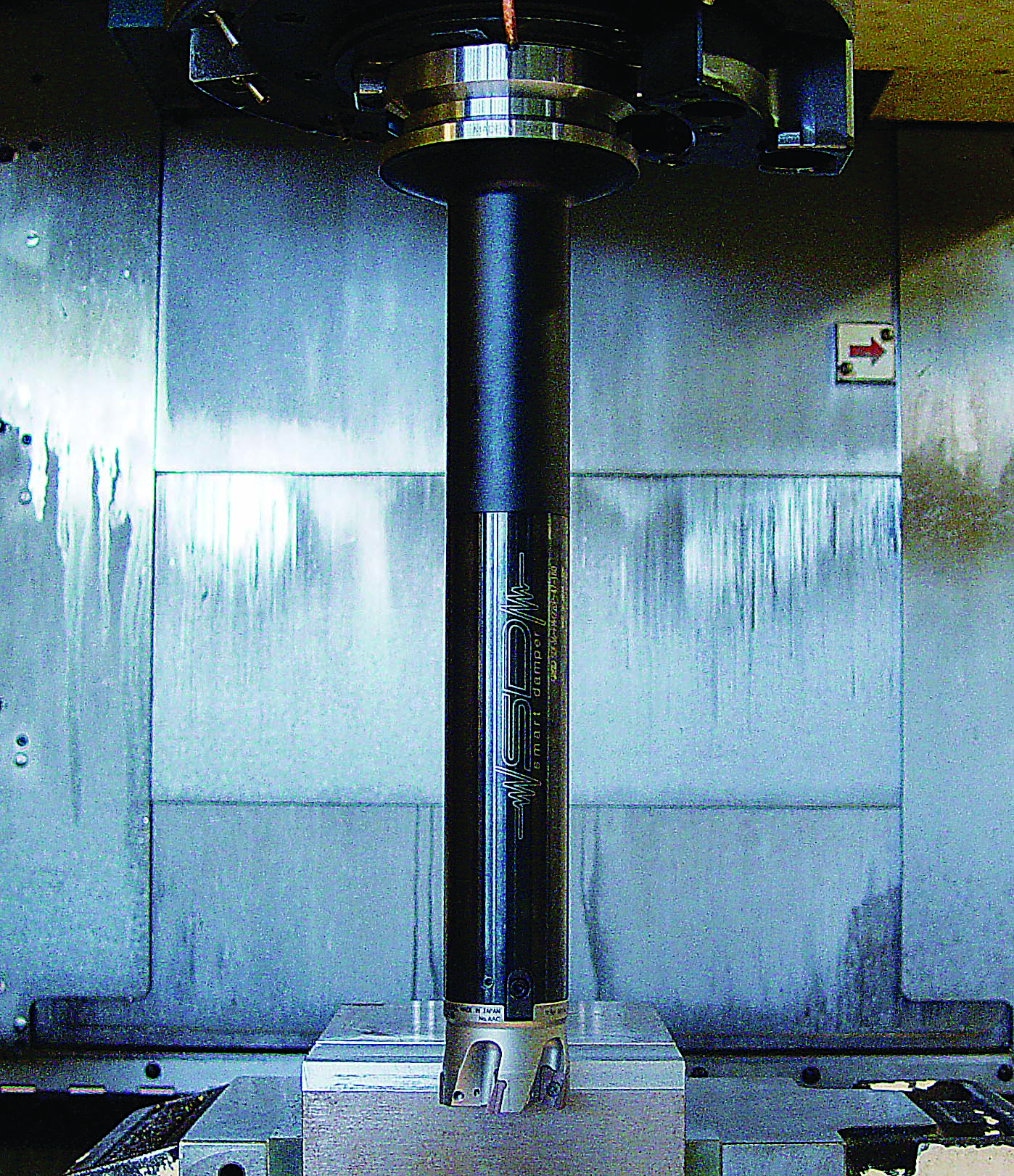
An integrated damping system for extended-reach facemilling eliminates vibration for higher productivity, better surface finishes and higher removal rates. Image courtesy of BIG KAISER Precision Tooling
The advantage of the modular concept, according to Burley, is that there are hundreds of different components that can be assembled together. A CAD/CAM programmer can choose from these to create the optimal tool configuration to fit into the reach and meet the needs of the program.
“It’s kind of like Legos where you start with a basic holder and you can extend it and taper it and do all kinds of things to make it the way you want it to look using standard components,” Burley said. “And the beauty of that is, because you’re using a pool of common components, you can take it apart whenever the job is over and reuse the parts for other builds.”
A modular system normally consists of basic holders with extensions, reductions and toolholder components that fit into them, such as shell mill, collet chuck or endmill holders.
Review the print ads from this magazine to continue
This quick advertiser review unlocks the rest of the article and keeps the full-screen reader focused on the ads instead of the page chrome.
Continue reading
July 2019