Embracing slot diversity

Author Alan Richter
Published
January 05, 2021 - 10:00am

Regardless of whether an end user plows a cutting tool into a workpiece material or takes small, light and fast cuts, slot milling can be hard, depending on the application.

“Taking a 3"-dia. (76.2 mm) cutter and burying it in titanium is pretty challenging,” said Luke Pollock, product manager for Walter USA LLC in Waukesha, Wisconsin. “Anything that is difficult to machine, like stainless steel, or where chip control is a big concern is always going to be a challenge.”

Effective chip evacuation is also a consideration when milling a deep slot or groove because re-cutting chips shortens tool life and chips can mar the surface finish, said Joseph DeRoss, Eastern U.S. milling specialist for Sandvik Coromant Co. in Fair Lawn, New Jersey. According to Dan Tucker, Western U.S. milling specialist, a slot is deep when a tool takes a cut at least two diameters deep. (Both men support the Central U.S.)

“As far as deep grooves,” Tucker said, “where you are going to have chip evacuation issues, horizontal machines are the preferred method.” 

Because of how parts usually are positioned for slotting, Greg Bronson, sales director of the Americas for Saegertown, Pennsylvania-based Greenleaf Corp., said most large-diameter slotting is performed on horizontal machining centers while many T-slot cutters and undercut tools are applied vertically.

He added curved slot milling to the list of challenges. End users that serve the aerospace or power generation industries perform that operation when producing bladed disks, or blisks, where the shape of the airfoil is curved.


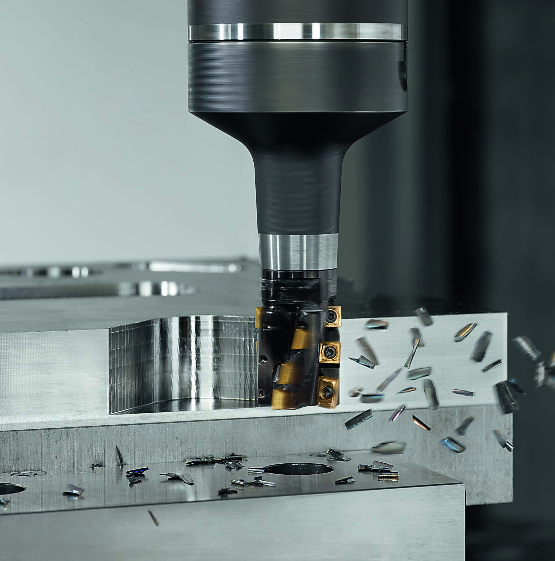
Walter USA offers a variety of tools for slot milling, including porcupine cutters.  Image courtesy of Walter USA

Bronson said Greenleaf designs cutters that go into curved shapes, “which is a challenge because you don’t have a straight line of sight through that slot like you would with traditional slotting. The tool is a little unusual. When you look at the side profile of a contact lens, it’s dished; that’s the shape of the cutter.”

Unlike most cutting tool manufacturers, he said 60% to 70% of the tools Greenleaf sells for slot milling are specials because the standard line from the company is fairly narrow.

“We do a lot of custom work for customers based on what their specific part needs are,” Bronson said.

For example, the toolmaker has produced slot mills with diameters as large as 660.4 mm (26").

When a blade is attached to a disk rather than being integral like a blisk, a connection that looks like a fir tree is needed, Bronson said. The feature frequently is rough- and finish-broached, but Greenleaf produces milling tools that can eliminate the need to rough-broach the slot, significantly reducing cycle time.

Tool Time

Because slots or grooves can be short or long, closed or open, straight or crooked, deep or shallow and wide or narrow, one type of tool does not suit all applications, according to Sandvik Coromant. Options include endmills, disc cutters, long-edge or helical cutters, and side mills and facemills.

When machining a slot that starts and ends open, for instance, Tucker recommends an indexable-insert disc cutter.

“You are not stopping in the part,” he said, “and 99% of the time a wheel cutter is more productive because you have more inserts in the cut than an indexable or solid-carbide endmill.”

Pollock said the DOC determines the type of tool to apply, with a facemill limited to the DOC capability based on insert size.

“If you need something more than that,” he said, “you need to use a helical mill that has multiple inserts than can make up the cutting edge depth. A helical tool has a long cutting edge; some call it a porcupine cutter.”


Greenleaf designs cutters that go into curved shapes, such as the airfoil of a blisk. Image courtesy of Greenleaf

In addition, a workpiece material influences the geometric features of a tool. Bronson said stringier materials, such as some high-temperature superalloys, require a tool with a positive geometry to more effectively shear the materials. He said a positive geometry also is recommended for cutting titanium and aluminum alloys.

On the flip side, he said a negative geometry is more appropriate for abrasive materials like cast iron.

“It gives you a little bit stronger edge and reduces edge breakdown,” Bronson said.

To help minimize edge chipping on positive tools, they typically have a small hone on the edge that measures from 0.0127 to 0.0254 mm (0.0005" to 0.001"), depending on the workpiece material and application, he said.

For severe slotting operations where trouble with vibration or edge chipping might occur, DeRoss suggests a heavy edge preparation.

“It might be positive,” he said, “but at the edge, there might be a little flat to help give it more strength.”

DeRoss said a highly positive edge usually reduces vibration while creating curled, manageable chips, but the more positive the edge, the weaker it becomes.

“You always want to push that limit but not to where you give up the edge strength,” he said.

Pollock concurred that an edge that’s too positive poses pitfalls.

“Particularly in soft materials,” he said, “it might have a tendency for the material to try and pull the cutter into it and pull it off its line of center. That can induce a lot of chatter.”

In addition to an edge preparation, DeRoss said applying a chemical vapor deposition coating strengthens the cutting edge of an insert, though the edge won’t be as sharp as one with a physical vapor deposition coating.


Indexable-insert wheel cutters with internal coolant, such as the CoroMill QD tool, are effective for groove milling. Image courtesy Sandvik Coromant

Tucker said that about a year ago Sandvik Coromant introduced Inveio coating technology, which further improves the ability to prevent cracks from forming on the edge line.

“It has a columnar structure,” he said. “The better those columnar structures are aligned, the better the ability to stop crack propagation in the milling process.”

Cool Cutting

To help with chip control for solid-carbide slotting tools, Pollock recommends using a chip splitter on the cutting edge.

“So instead of taking a deep depth of cut and long chips in the axial direction,” he said, “with chip splitters along the cutting edge, you get short chips in the axial direction.”

Rather than coolant, Pollock said he prefers chip splitters to aid chip evacuation, if possible. In addition, he discourages using high-pressure coolant, which generally requires a pressure of 69 bar (1,000 psi) or higher.

“I almost never want to use that type of coolant system with milling because it can induce so much vibration into the application,” he said.

Although Tucker typically recommends high-pressure, through-tool coolant, he said too much coolant pressure in a cutter creates vibration, especially when slotting or grooving aluminum at high speeds and feeds.

“You can get a vortex situation inside a groove where the pressure is so great that the cutter starts vibrating,” he said. “There is a fine line there, but it’s usually a condition of how fast you are spinning that cutter.”

Bronson said flood coolant is more beneficial than high-pressure coolant when slotting to control the temperature of a part and keeps its dimensional criteria stable.

“It’s very unusual for us to see 1,000-to-1,500-psi applications in indexable slotting,” he said.

Using an air blast or chilled air is another option for keeping a part and tool cool when slotting. Bronson said an air blast or chilled air is recommended for slotting with ceramic inserts, which Greenleaf has a long tradition of producing. Air cools a part and tool and helps remove chips from a toolpath, extending tool life. In addition to uncoated ceramic inserts, the toolmaker offers coated ones, which resist heat, can increase lubricity and add a thermal layer to prevent chemical erosion when machining.

As recently as five years ago, ceramics were considered a niche area limited to the types of materials they could cut effectively, such as silicon nitride for cast iron and whisker-reinforced ceramics for high-temperature superalloys and hardened materials. He said that changed with Greenleaf’s introduction of its Xsytin-1 multipurpose ceramic grade, which is suitable for machining cast and ductile iron, high-temperature alloys, steel, stainless steel and other challenging-to-machine metals.

A Suitable Approach

There are three basic slot milling techniques: conventional, plunge and trochoidal, or dynamic.

With conventional slot milling, Pollock said the tool runs straight through in an x-to-y move and takes a full WOC.


An example of a slotting cutter is shown. Image courtesy of Greenleaf

“You are a little bit limited in the number of teeth you can use because you need more flute space,” he said, “so the material that you are removing has to fit into that flute space and be evacuated.”

Pollock said another limitation is the feed per tooth and cutting speed that the tool can run at based on the rigidity of the machine and how much force the tool can withstand before fracturing.

Plunge milling is a problem-solver in vibration-sensitive applications, such as those with long tool overhangs, when deep slotting and when a weak setup can’t be overcome, Sandvik Coromant reports. However, plunging provides a low level of productivity under stable conditions and requires a rest milling or finishing operation, and the selection of suitable tools is limited.

Pollock said when dynamic slot milling, the cutter takes smaller, lighter and faster cuts than when conventional slotting and usually is performed on highly agile machines with smaller spindle connections than are found on the massive machines used for conventional approaches.

“We are definitely seeing a trend in that direction for increasing the metal removal rate,” he said.

Tucker said older machines, however, may not be capable of taking a big length of cut with light step-overs that dynamic slotting requires.

“We are always going to recommend solutions based on productivity,” he said. “In order to get that productivity, you have to use some of these light and fast approaches.”

Of course, end users typically balk at investing in a new machine tool to boost the productivity of a cutting tool when the current machine isn’t broken, but a cutter might enable a lower capital investment when one already is planned. Bronson recalled a customer that was taking at least 30 minutes to conventionally produce a slot and was expecting to purchase 100 machines over a two-to-three-year period because of the customer’s high-volume requirements. After Greenleaf designed a cutter to increase the removal rate and complete the same operation in about four minutes, the customer then needed to purchase significantly fewer machines.

Pollock said although virtually every part manufacturer has at least someone at the shop who’s familiar with dynamic milling, some people resist change and it can be challenging to convince everyone to go in that direction.

“If you have been at this for 20 years,” he said, “it’s kind of hard to get your head around it and that you can actually machine a material that fast.”  


For more information about slot milling, view a video presentation by Sandvik Coromant at www.ctemag.com by scanning the QR code on your smartphone or entering this URL on your web browser: cteplus.delivr.com/2an3a


Related Glossary Terms

  • abrasive

    abrasive

    Substance used for grinding, honing, lapping, superfinishing and polishing. Examples include garnet, emery, corundum, silicon carbide, cubic boron nitride and diamond in various grit sizes.

  • alloys

    alloys

    Substances having metallic properties and being composed of two or more chemical elements of which at least one is a metal.

  • aluminum alloys

    aluminum alloys

    Aluminum containing specified quantities of alloying elements added to obtain the necessary mechanical and physical properties. Aluminum alloys are divided into two categories: wrought compositions and casting compositions. Some compositions may contain up to 10 alloying elements, but only one or two are the main alloying elements, such as copper, manganese, silicon, magnesium, zinc or tin.

  • centers

    centers

    Cone-shaped pins that support a workpiece by one or two ends during machining. The centers fit into holes drilled in the workpiece ends. Centers that turn with the workpiece are called “live” centers; those that do not are called “dead” centers.

  • ceramics

    ceramics

    Cutting tool materials based on aluminum oxide and silicon nitride. Ceramic tools can withstand higher cutting speeds than cemented carbide tools when machining hardened steels, cast irons and high-temperature alloys.

  • chatter

    chatter

    Condition of vibration involving the machine, workpiece and cutting tool. Once this condition arises, it is often self-sustaining until the problem is corrected. Chatter can be identified when lines or grooves appear at regular intervals in the workpiece. These lines or grooves are caused by the teeth of the cutter as they vibrate in and out of the workpiece and their spacing depends on the frequency of vibration.

  • chemical vapor deposition ( CVD)

    chemical vapor deposition ( CVD)

    High-temperature (1,000° C or higher), atmosphere-controlled process in which a chemical reaction is induced for the purpose of depositing a coating 2µm to 12µm thick on a tool’s surface. See coated tools; PVD, physical vapor deposition.

  • coolant

    coolant

    Fluid that reduces temperature buildup at the tool/workpiece interface during machining. Normally takes the form of a liquid such as soluble or chemical mixtures (semisynthetic, synthetic) but can be pressurized air or other gas. Because of water’s ability to absorb great quantities of heat, it is widely used as a coolant and vehicle for various cutting compounds, with the water-to-compound ratio varying with the machining task. See cutting fluid; semisynthetic cutting fluid; soluble-oil cutting fluid; synthetic cutting fluid.

  • cutting speed

    cutting speed

    Tangential velocity on the surface of the tool or workpiece at the cutting interface. The formula for cutting speed (sfm) is tool diameter 5 0.26 5 spindle speed (rpm). The formula for feed per tooth (fpt) is table feed (ipm)/number of flutes/spindle speed (rpm). The formula for spindle speed (rpm) is cutting speed (sfm) 5 3.82/tool diameter. The formula for table feed (ipm) is feed per tooth (ftp) 5 number of tool flutes 5 spindle speed (rpm).

  • depth of cut

    depth of cut

    Distance between the bottom of the cut and the uncut surface of the workpiece, measured in a direction at right angles to the machined surface of the workpiece.

  • edge preparation

    edge preparation

    Conditioning of the cutting edge, such as a honing or chamfering, to make it stronger and less susceptible to chipping. A chamfer is a bevel on the tool’s cutting edge; the angle is measured from the cutting face downward and generally varies from 25° to 45°. Honing is the process of rounding or blunting the cutting edge with abrasives, either manually or mechanically.

  • endmill

    endmill

    Milling cutter held by its shank that cuts on its periphery and, if so configured, on its free end. Takes a variety of shapes (single- and double-end, roughing, ballnose and cup-end) and sizes (stub, medium, long and extra-long). Also comes with differing numbers of flutes.

  • facemill

    facemill

    Milling cutter for cutting flat surfaces.

  • feed

    feed

    Rate of change of position of the tool as a whole, relative to the workpiece while cutting.

  • flat ( screw flat)

    flat ( screw flat)

    Flat surface machined into the shank of a cutting tool for enhanced holding of the tool.

  • gang cutting ( milling)

    gang cutting ( milling)

    Machining with several cutters mounted on a single arbor, generally for simultaneous cutting.

  • grooving

    grooving

    Machining grooves and shallow channels. Example: grooving ball-bearing raceways. Typically performed by tools that are capable of light cuts at high feed rates. Imparts high-quality finish.

  • lubricity

    lubricity

    Measure of the relative efficiency with which a cutting fluid or lubricant reduces friction between surfaces.

  • milling

    milling

    Machining operation in which metal or other material is removed by applying power to a rotating cutter. In vertical milling, the cutting tool is mounted vertically on the spindle. In horizontal milling, the cutting tool is mounted horizontally, either directly on the spindle or on an arbor. Horizontal milling is further broken down into conventional milling, where the cutter rotates opposite the direction of feed, or “up” into the workpiece; and climb milling, where the cutter rotates in the direction of feed, or “down” into the workpiece. Milling operations include plane or surface milling, endmilling, facemilling, angle milling, form milling and profiling.

  • milling machine ( mill)

    milling machine ( mill)

    Runs endmills and arbor-mounted milling cutters. Features include a head with a spindle that drives the cutters; a column, knee and table that provide motion in the three Cartesian axes; and a base that supports the components and houses the cutting-fluid pump and reservoir. The work is mounted on the table and fed into the rotating cutter or endmill to accomplish the milling steps; vertical milling machines also feed endmills into the work by means of a spindle-mounted quill. Models range from small manual machines to big bed-type and duplex mills. All take one of three basic forms: vertical, horizontal or convertible horizontal/vertical. Vertical machines may be knee-type (the table is mounted on a knee that can be elevated) or bed-type (the table is securely supported and only moves horizontally). In general, horizontal machines are bigger and more powerful, while vertical machines are lighter but more versatile and easier to set up and operate.

  • physical vapor deposition ( PVD)

    physical vapor deposition ( PVD)

    Tool-coating process performed at low temperature (500° C), compared to chemical vapor deposition (1,000° C). Employs electric field to generate necessary heat for depositing coating on a tool’s surface. See CVD, chemical vapor deposition.

  • plunge milling

    plunge milling

    Highly productive method of metal removal in which an axial machining operation is performed in a single tool sequence. The tool makes a series of overlapping, drill-like plunges to remove part of a cylindrical plug of material one after another. Because of the increased rigidity of a Z-axis move, the tool can cover a large cross-section of material.

  • slotting

    slotting

    Machining, normally milling, that creates slots, grooves and similar recesses in workpieces, including T-slots and dovetails.

  • superalloys

    superalloys

    Tough, difficult-to-machine alloys; includes Hastelloy, Inconel and Monel. Many are nickel-base metals.

  • toolpath( cutter path)

    toolpath( cutter path)

    2-D or 3-D path generated by program code or a CAM system and followed by tool when machining a part.

  • undercut

    undercut

    In numerical-control applications, a cut shorter than the programmed cut resulting after a command change in direction. Also a condition in generated gear teeth when any part of the fillet curve lies inside of a line drawn tangent to the working profile at its point of juncture with the fillet. Undercut may be deliberately introduced to facilitate finishing operations, as in preshaving.

  • web

    web

    On a rotating tool, the portion of the tool body that joins the lands. Web is thicker at the shank end, relative to the point end, providing maximum torsional strength.

Author

Editor-at-large

Alan holds a bachelor’s degree in journalism from Southern Illinois University Carbondale. Including his 20 years at CTE, Alan has more than 30 years of trade journalism experience.

Contributors 

Greenleaf Corp.
814-763-2915
www.greenleafcorporation.com

Sandvik Coromant Co.
800-726-3845
www.sandvik.coromant.com

Walter USA LLC
800-945-5554
www.walter-tools.com