Efficiently remove material: Design & Engineering
Dynamic Motion application provides constant chip load machining with efficient cutting conditions.
The evolution of efficiently removing material has basically unfolded like this:
Traditional machining. We used the speeds and feeds recommended in catalogs from cutting tool manufacturers. We cut a 50% step-over as a rule of thumb, and while maybe it wasn’t the most efficient process in the world, we didn’t know the difference.
Radial chip thinning. We still used the machining parameters from the cutting tool catalogs, yet we were also able to increase the feed rates and metal removal rates when stepping over less than 50% of the tool diameter. We began to increase productivity—when we went in a straight line, that is. Fluctuations in tool load continued to limit productivity.
Dynamic Motion. This is where we have been for about 10 years. We started with the radial chip thinning principles and have been increasing feed rates, step-downs and removal rates. The cutting tool motion modifies dynamically to produce consistent, optimal chips—we call this constant chip load machining—and offers efficient cutting conditions regardless of workpiece geometry.
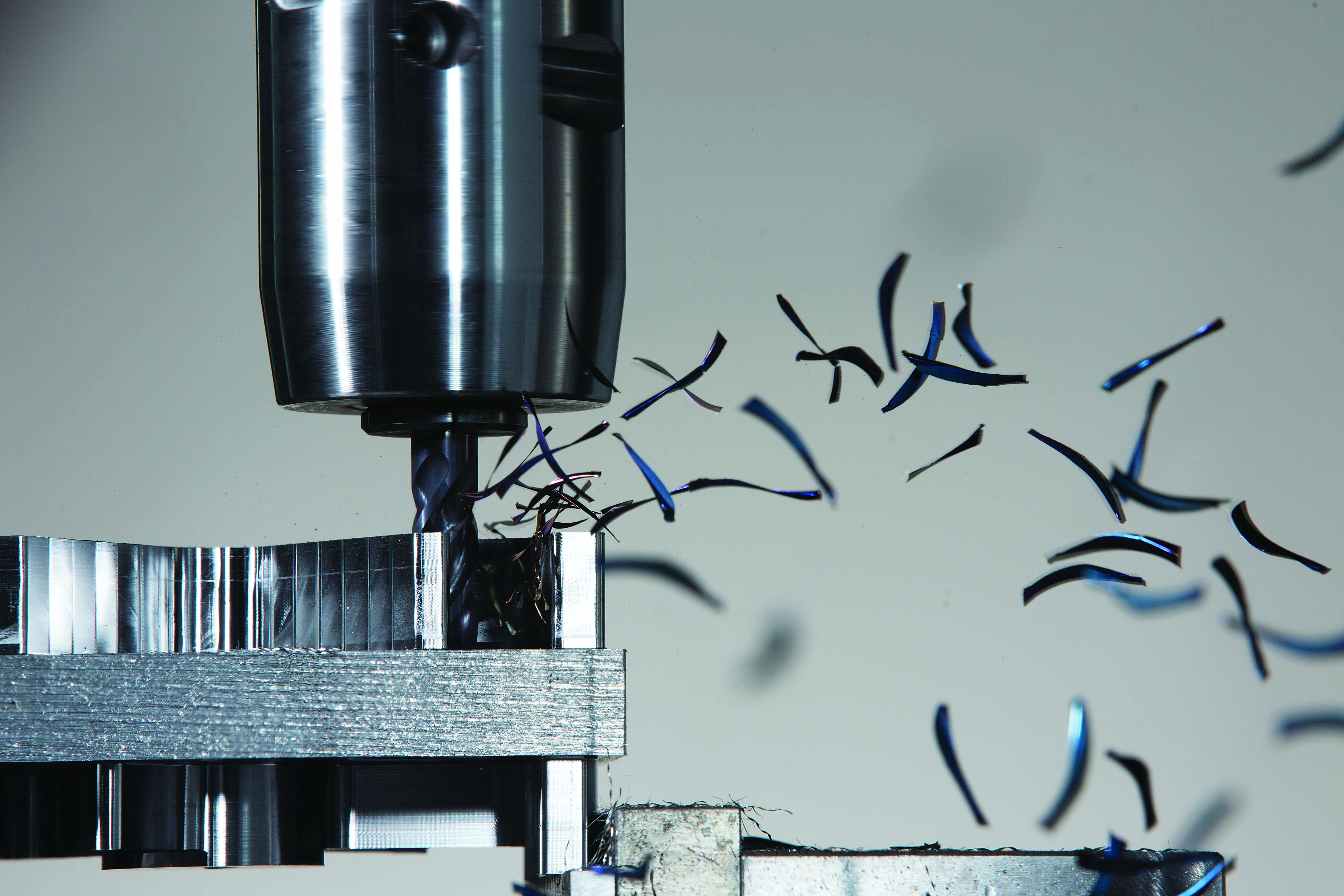
With Dynamic Motion, cutting tool motion modifies dynamically to produce consistent, optimal chips. Image courtesy of CNC Software
For several years, the Dynamic Motion application has proven itself again and again for those who have adopted these material-aware toolpaths. As always, we learn from customers who use our software in the real world day in, day out. They eagerly tell us about their successes and challenges. With each release of our software package, we tweak this or that based on their valuable feedback.
Review the print ads from this magazine to continue
This quick advertiser review unlocks the rest of the article and keeps the full-screen reader focused on the ads instead of the page chrome.


