Whether you’re a truck driver, a commercial airline pilot or a snowmobiler, a leaky hydraulic system or fuel line can spell big trouble. A little fluid in the wrong place on these and a host of other vehicles and machinery might create a life-or-death situation for operators and passengers alike.
That’s why organizations like SAE (Society of Automotive Engineers) and ISO (International Standards Organization) have developed a series of standards that make even the highest-pressure, most-demanding fluid connection leak-free. These include SAE J1926, SAE J514, MS 33649/SAE AS5202, ISO 6149 and other technical documents that describe threaded connections.
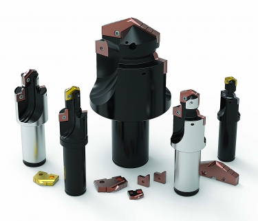
Some fluid connectors come with O-rings, others with metal-on-metal seals, but all rely on a complex shape that is usually machined with a port tool.
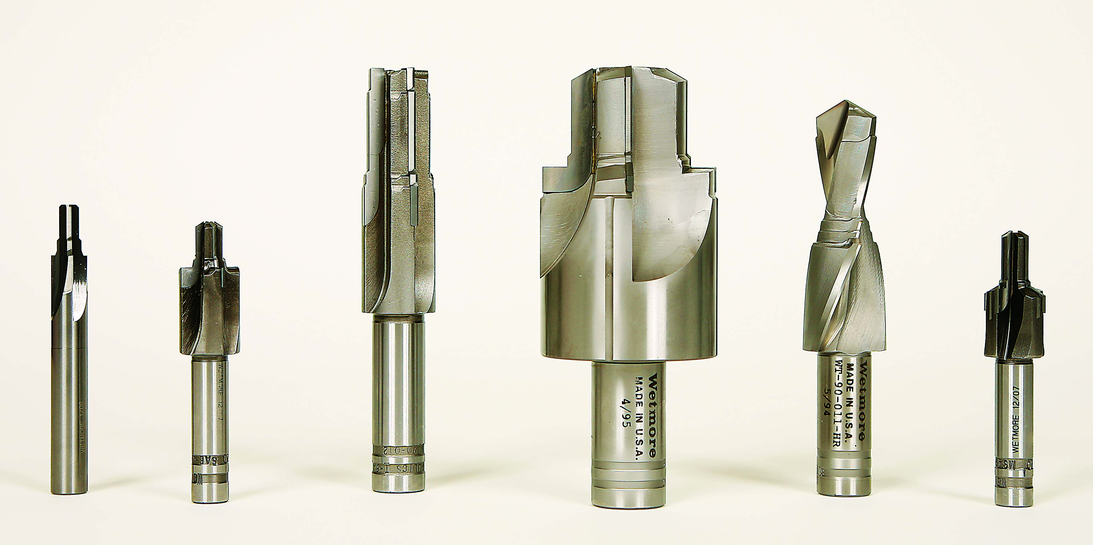
Port tools can be resharpened many times and, according to Wetmore Tool, may last decades. Photo courtesy of Wetmore Tool and Engineering.
It’s Scientific
Dale Christopher, president of Scientific Cutting Tools Inc. (SCT), Simi Valley, Calif., said his father built the business on port tools. Even though that source of revenue has fallen relative to the other types of cutting tools the company now offers, there’s still plenty of demand from hydraulic-manifold manufacturers, automotive and aerospace customers, and electromechanical equipment suppliers.
For those scratching their heads over the bewildering array of port specifications, the situation’s not as complicated as it first seems. “The military came up with a standard hydraulic connector many years ago for connecting hose lines to hydraulic fittings,” Christopher said. “That was the start of the MS (mil-spec) standards. Some are still the
original Army or Navy design, but quite a few have been replaced by SAE numbers.”
Nor are ports as complex as they initially appear. “It’s really just a series of diameters and angles,” he said. “Sometimes you’ll have radii callouts and sealing surfaces with tight finish requirements. Because ports are used with a connector, there’s a thread somewhere, usually at the bottom, that can be tapped, thread-milled or single-pointed if you’re turning the part on a lathe.”
Porting is not rocket science. However, the configurations are sufficiently complex that they would be extremely challenging to make on most machines without what is essentially a big form tool. CNC lathes make it possible to shelve port tools in favor of a boring bar and CAM-generated toolpath. Still, port tools remain commonplace on machining centers, mechanical screw machines and even drill presses, where profiling the port shape is impossible.
Port Popularity
“Porting on a drill press or transfer line requires a tool with a ground body so it can slide into a bushing mounted in a drill plate to guide the tool into the workpiece,” said Phil Kurtz, vice chairman of the board at Wetmore Tool and Engineering Co., Chino, Calif. “But those tools are rarely used anymore because hardly anyone uses drill presses. Virtually everything is made on CNC machines today.”
Other port tools have also seen a decline in popularity. Kurtz said the company has a long history of manufacturing port tools, but much of the work has dried up as aircraft designers move away from specifying hydraulic control systems in favor of electronic ones. As a result, Wetmore has redirected most of its development efforts into aircraft assembly tools, such as extension and core drills.
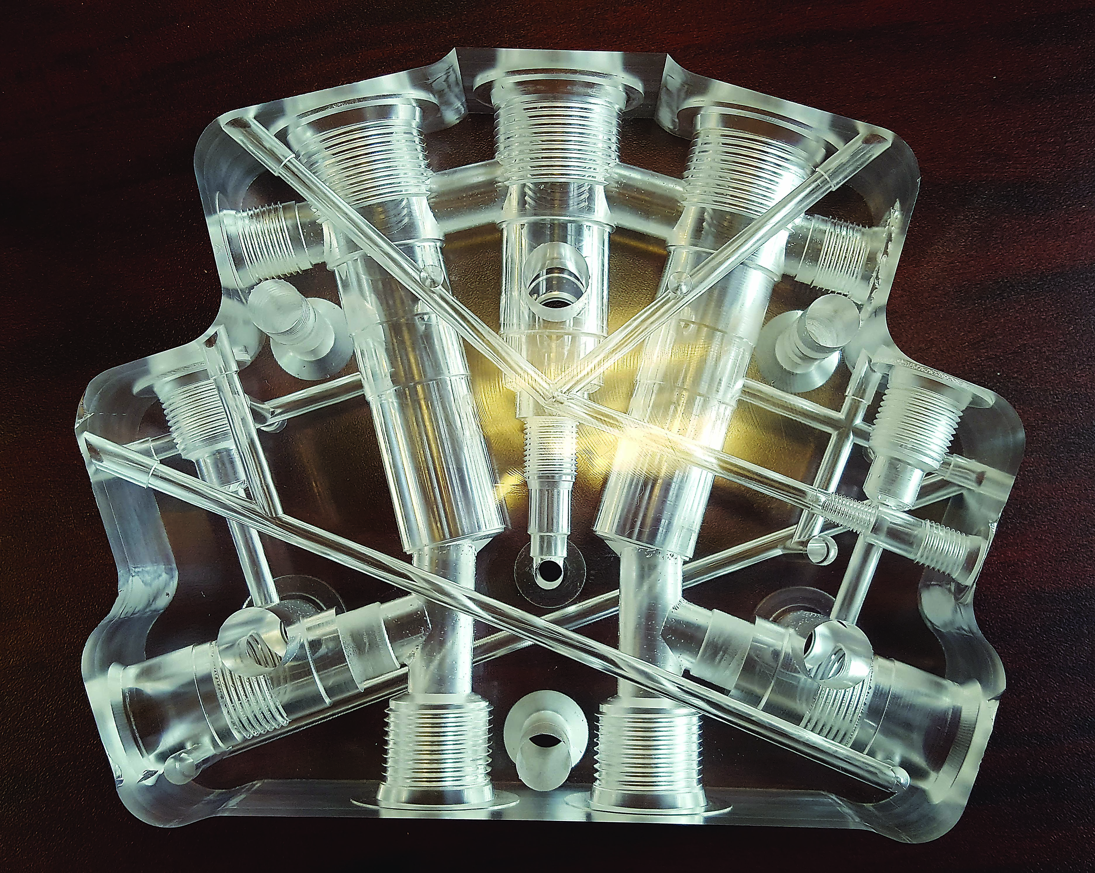
A mock-up of a ported agricultural valve body for a trade show presentation. Image courtesy of New Dimensions Precision Machining.
“We still see a fair amount of activity with standard brazed porting tools, but it’s not like it once was,” Kurtz said. He added that cartridge cavity tools remain fairly strong. “These are quite similar to port tools but larger, to accommodate a two-, three- or four-way hydraulic valve body that might be used to control a backhoe, for example.”
Keep Quiet
One of the biggest challenges with any porting operation is chatter. SCT’s Christopher said a 3-flute port tool is often effective in combating chatter. However, the feed rate is sacrificed because there’s one less edge in the cut compared to the more-common 4-flute port tool. “That’s why we take a diamond brush hone to all our tools,” he said. “This puts a microscopic edge break on the sharp edges. [It is] a little like rubbing a penny or a Scotch-Brite pad on the tool’s spot face, a trick that many veteran machinists are familiar with.”
This is good advice. Anyone who’s used port tools knows that they generally work best after a short wear-in period. They also last a surprisingly long time.
Someone who can speak to this is Bill Jones, president of Enderle Fuel Injection Inc., Simi Valley, Calif. He recently broke a tool he’d been using for the past 10 years. “I was hoping to get an 11th year out of it,” he laughed.
Enderle applies SCT tools to port barrel valves, fuel shutoffs, fittings and other racing equipment components. Most of these are made of 6061-T6 aluminum, although Jones said Enderle machines some cast aluminum, which is somewhat abrasive. Still, he and his team have “zero problems” with tool life or chatter—success that Jones attributed to a rigid setup and high-quality cutting tools.
Porting in the Heartland
Another porting success story comes from Union, Ill. Brian Halwix Sr., director of manufacturing engineering at New Dimensions Precision Machining Inc., said the company produces a variety of aluminum and cast iron hydraulic manifolds for the agriculture and construction industries on its three Makino flexible-manufacturing systems, which utilize 19 horizontal machining centers. For Halwix, the biggest challenge with port machining is breaking into cross-holes.
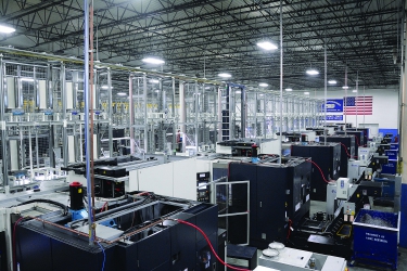
The 19-machine FMS at New Dimensions produces a variety of aluminum and cast iron hydraulic manifolds for the agriculture and construction industries. Image courtesy of New Dimensions Precision Machining.
“Porting is pretty straightforward otherwise,” he said. “But when the tool breaks through into a neighboring hole, it tends to lose stability, causing problems with straightness and position.” Halwix added that roundness is also a concern, especially when maintaining a 0.33 Cpk allowance of ± 0.0013" (0.03mm). “The hole can easily end up egg-shaped if you don’t control the cutting forces.”
Halwix said there are two ways to avoid this problem. The first is proper part processing, particularly machining ports in the right order to avoid cross-holes in the first place. The next course of action is tweaking the tool design by adjusting flute margins and using other tricks of the porting trade. “It’s all about cutter technology,” he said. “That’s why probably 30 percent of our tools are custom, which we designed in-house based on our own education and experience.”
Hartland Cutting Tools Inc., Cary, Ill., is near New Dimensions. Owner Mike Polizzi said he provides solid and carbide-tipped port tools, although HSS and indexable versions are available from other suppliers. Customers must also decide on the style of tool to apply:
- Solid pilot port tools have a noncutting button on the end that requires a previously bored or reamed hole “a few thousandths” larger than the button diameter. The button rides within this bore, which helps to guide and support the tool during machining.
- Reamer-style tools, which are self-piloting, are probably the most common type of port tool. Simply drill a starter hole slightly smaller than the port’s smallest diameter and the port tool does the rest.
- “One-shot” tools are able to drill, ream and port in one operation, eliminating the need for a starter hole. They also save machining time.
“Port tools have become quite specialized and high-performance over the years,” Polizzi said. His company still offers the same standard tools that were in use 30 years ago. However, according to Polizzi, companies like Eaton, Vickers, Hydac and Sun Hydraulics have all developed their own application-specific geometries. “Most of these are straight-flute tools, but some have a slight helix to improve finish and size control. Sometimes we’ll grind the flutes off-center a small amount for customers machining a lot of aluminum.”
As with any indexable cutting tool, these port tools increase uptime. Just change the insert and go back to work. Image courtesy of Allied Machine and Engineering.
Polizzi said most of his clients want through-coolant tools, something he heartily endorses. He recommends 1,000 psi, whenever possible, and the use of a high-quality toolholder, preferably a hydraulic chuck rather than an endmill holder. “Drill the port, dwell for a second or two at the bottom of the hole and you’ll be in good shape.”
The Indexable Story
What about port tools with indexable carbide inserts? Solid-carbide and brazed tool aficionados might disagree, but for many applications, indexable tools are suitable. “Aside from the threads, our tool cuts the entire port in one operation,” said Rob Brown, product manager at Allied Machine and Engineering Corp., Dover, Ohio. “When it gets dull, you just change out the insert and go back to work. You don’t have to worry about regrinding or knocking out the old carbide and brazing in new pieces.”
Brown said indexable cutters are also more cost effective. Each insert costs around $35 to $70, and a dual-insert cutter body runs roughly $600, depending on the size. This is about twice the cost of a comparable brazed tool, but Brown said users of traditional port tools need to have multiple cutters: one in the machine, a spare in the toolcrib and one out for regrinding.
“With indexable cutters, you need a couple of spare inserts and screws,” he said. “And there’s no need to spot-drill, drill and rough the port form as there is with traditional port tools. You just come in and drill, and the port’s ready to go. Because you’re not worried as much about tool life, you can be a bit more aggressive on feeds and speeds. The end result is a lower cost per part.”
Contact Details
Contact Details
Contact Details
Related Glossary Terms
- abrasive
abrasive
Substance used for grinding, honing, lapping, superfinishing and polishing. Examples include garnet, emery, corundum, silicon carbide, cubic boron nitride and diamond in various grit sizes.
- boring
boring
Enlarging a hole that already has been drilled or cored. Generally, it is an operation of truing the previously drilled hole with a single-point, lathe-type tool. Boring is essentially internal turning, in that usually a single-point cutting tool forms the internal shape. Some tools are available with two cutting edges to balance cutting forces.
- boring bar
boring bar
Essentially a cantilever beam that holds one or more cutting tools in position during a boring operation. Can be held stationary and moved axially while the workpiece revolves around it, or revolved and moved axially while the workpiece is held stationary, or a combination of these actions. Installed on milling, drilling and boring machines, as well as lathes and machining centers.
- bushing
bushing
Cylindrical sleeve, typically made from high-grade tool steel, inserted into a jig fixture to guide cutting tools. There are three main types: renewable, used in liners that in turn are installed in the jig; press-fit, installed directly in the jig for short production runs; and liner (or master), installed permanently in a jig to receive renewable bushing.
- centers
centers
Cone-shaped pins that support a workpiece by one or two ends during machining. The centers fit into holes drilled in the workpiece ends. Centers that turn with the workpiece are called “live” centers; those that do not are called “dead” centers.
- chatter
chatter
Condition of vibration involving the machine, workpiece and cutting tool. Once this condition arises, it is often self-sustaining until the problem is corrected. Chatter can be identified when lines or grooves appear at regular intervals in the workpiece. These lines or grooves are caused by the teeth of the cutter as they vibrate in and out of the workpiece and their spacing depends on the frequency of vibration.
- chuck
chuck
Workholding device that affixes to a mill, lathe or drill-press spindle. It holds a tool or workpiece by one end, allowing it to be rotated. May also be fitted to the machine table to hold a workpiece. Two or more adjustable jaws actually hold the tool or part. May be actuated manually, pneumatically, hydraulically or electrically. See collet.
- computer numerical control ( CNC)
computer numerical control ( CNC)
Microprocessor-based controller dedicated to a machine tool that permits the creation or modification of parts. Programmed numerical control activates the machine’s servos and spindle drives and controls the various machining operations. See DNC, direct numerical control; NC, numerical control.
- drilling machine ( drill press)
drilling machine ( drill press)
Machine designed to rotate end-cutting tools. Can also be used for reaming, tapping, countersinking, counterboring, spotfacing and boring.
- endmill
endmill
Milling cutter held by its shank that cuts on its periphery and, if so configured, on its free end. Takes a variety of shapes (single- and double-end, roughing, ballnose and cup-end) and sizes (stub, medium, long and extra-long). Also comes with differing numbers of flutes.
- feed
feed
Rate of change of position of the tool as a whole, relative to the workpiece while cutting.
- flexible manufacturing system ( FMS)
flexible manufacturing system ( FMS)
Automated manufacturing system designed to machine a variety of similar parts. System is designed to minimize production changeover time. Computers link machine tools with the workhandling system and peripherals. Also associated with machine tools grouped in cells for efficient production. See cell manufacturing.
- flutes
flutes
Grooves and spaces in the body of a tool that permit chip removal from, and cutting-fluid application to, the point of cut.
- high-speed steels ( HSS)
high-speed steels ( HSS)
Available in two major types: tungsten high-speed steels (designated by letter T having tungsten as the principal alloying element) and molybdenum high-speed steels (designated by letter M having molybdenum as the principal alloying element). The type T high-speed steels containing cobalt have higher wear resistance and greater red (hot) hardness, withstanding cutting temperature up to 1,100º F (590º C). The type T steels are used to fabricate metalcutting tools (milling cutters, drills, reamers and taps), woodworking tools, various types of punches and dies, ball and roller bearings. The type M steels are used for cutting tools and various types of dies.
- lathe
lathe
Turning machine capable of sawing, milling, grinding, gear-cutting, drilling, reaming, boring, threading, facing, chamfering, grooving, knurling, spinning, parting, necking, taper-cutting, and cam- and eccentric-cutting, as well as step- and straight-turning. Comes in a variety of forms, ranging from manual to semiautomatic to fully automatic, with major types being engine lathes, turning and contouring lathes, turret lathes and numerical-control lathes. The engine lathe consists of a headstock and spindle, tailstock, bed, carriage (complete with apron) and cross slides. Features include gear- (speed) and feed-selector levers, toolpost, compound rest, lead screw and reversing lead screw, threading dial and rapid-traverse lever. Special lathe types include through-the-spindle, camshaft and crankshaft, brake drum and rotor, spinning and gun-barrel machines. Toolroom and bench lathes are used for precision work; the former for tool-and-die work and similar tasks, the latter for small workpieces (instruments, watches), normally without a power feed. Models are typically designated according to their “swing,” or the largest-diameter workpiece that can be rotated; bed length, or the distance between centers; and horsepower generated. See turning machine.
- precision machining ( precision measurement)
precision machining ( precision measurement)
Machining and measuring to exacting standards. Four basic considerations are: dimensions, or geometrical characteristics such as lengths, angles and diameters of which the sizes are numerically specified; limits, or the maximum and minimum sizes permissible for a specified dimension; tolerances, or the total permissible variations in size; and allowances, or the prescribed differences in dimensions between mating parts.
- profiling
profiling
Machining vertical edges of workpieces having irregular contours; normally performed with an endmill in a vertical spindle on a milling machine or with a profiler, following a pattern. See mill, milling machine.
- toolholder
toolholder
Secures a cutting tool during a machining operation. Basic types include block, cartridge, chuck, collet, fixed, modular, quick-change and rotating.
- toolpath( cutter path)
toolpath( cutter path)
2-D or 3-D path generated by program code or a CAM system and followed by tool when machining a part.
- turning
turning
Workpiece is held in a chuck, mounted on a face plate or secured between centers and rotated while a cutting tool, normally a single-point tool, is fed into it along its periphery or across its end or face. Takes the form of straight turning (cutting along the periphery of the workpiece); taper turning (creating a taper); step turning (turning different-size diameters on the same work); chamfering (beveling an edge or shoulder); facing (cutting on an end); turning threads (usually external but can be internal); roughing (high-volume metal removal); and finishing (final light cuts). Performed on lathes, turning centers, chucking machines, automatic screw machines and similar machines.
Author

Kip Hanson is a contributing editor for Cutting Tool Engineering magazine. Contact him by phone at (520) 548-7328 or via e-mail at [email protected].
Contributors
Allied Machine and Engineering Corp.
(330) 343-4283
www.alliedmachine.com
Enderle Fuel Injection Inc.
(805) 526-3838
Hartland Cutting Tools Inc.
(800) 535-4278
www.hartlandtool.com
New Dimensions Precision Machining Inc.
(815) 923-8300
www.newdims.com
Scientific Cutting Tools Inc.
(805) 584-9495
www.sct-usa.com
Wetmore Tool and Engineering Co.
(800) 708-3713
www.hpwetmore.com