Machining large compacted graphite iron castings for diesel engine components is challenging, but applying the proper tools and techniques can help.
Regardless of the fluctuations in the price of diesel fuel, the usage trend is upward while emission requirements head south. To remain competitive, producers of diesel components—especially engine blocks and cylinder heads—must provide parts that are lighter to reduce fuel consumption while providing the required performance characteristics. While aluminum engine blocks enable “lightweighting” compared to gray cast iron ones and continue to gain market share, iron is still needed for large-truck engines and high-torque engines in lighter vehicles.
“Those engines get pretty hot and there’s more concern about the engine failing so they use iron,” said Dick Schultz, project consultant for Ducker Worldwide, Troy, Mich., adding that up to 72 percent of engine blocks are aluminum now and that share will probably rise to 95 percent by 2015.
To lightweight those components that still need to be made of iron, part manufacturers are switching from gray cast iron to compacted graphite iron, which is a stronger material because it has about a 70 percent higher tensile strength and 45 percent greater stiffness and therefore can be used to make a lighter engine block with improved performance. “Manufacturers can thin the walls and webs so they end up with a CGI block that is lighter than the original aluminum block,” said Stan Weidmer, process development engineer for machine tool builder Makino Inc., Mason, Ohio. “That’s just mind-blowing.”
When an auto part must be made of iron, gray iron has a cost advantage vs. CGI because the latter is a highly engineered material. That means CGI is more difficult to produce at the foundry than gray iron, requiring tighter control of the alloying elements. Those include manganese, magnesium, chromium and titanium. For example, a foundry must hold magnesium content to a 0.003 percent tolerance.
“At the foundries, it’s tricky to get a very specific cocktail or recipe for CGI,” Weidmer said. “They stumbled on it by accident, but then it was difficult to repeat.” That occurred in the mid-’70s as a result of an off-spec melt of ductile iron. It’s often said CGI is a special form of ductile iron—an especially bad one. “If you were to lay these three irons side by side, you’d have gray on the left, ductile in the middle and CGI, which is the most difficult to machine, on the right,” Weidmer said.
Weidmer added, however, that various CGI grades exist. “There is not one standard CGI,” he said. “The real trick is figuring out exactly what’s in it and then customizing your speeds, feeds and DOCs based around that particular material.”
Slow Down, Live Less
One element CGI doesn’t include is sulfur because, with it, the desired graphite shape could not be achieved. The graphite shape in CGI is vermicular, or wormlike. In contrast, gray iron has a flaky graphite structure that’s relatively easy to machine and ductile iron’s graphite structure is nodular, or spheroid- al, and those nodules are surrounded by an abrasive silicon-carbide shell. According to Makino, in the case of gray iron, sulfur combines with the manganese in the iron and deposits itself on an insert, enabling carbide tools to be run at two to three times normal cutting speeds and PCBN to machine at advanced speeds because of this coating.

Courtesy of Sandvik Coromant
Sandvik Coromant reports that its K20W-grade insert with CGI-optimized KX positive geometries imparts a fine finish and minimizes burrs. formation.
Without the sulfur, auto part manufacturers experience a significant reduction in tool life and cutting speeds when cutting CGI. When milling CGI, for example, tool life is 40 to 50 percent shorter compared to milling gray iron, according to Jose R. Gamarra, engineering manager for Sandvik do (São Paulo) Brasil S.A. He added that the toolmaker recommends reducing the cutting speed by 40 percent for CGI vs. gray iron. “For example, in a milling operation for gray cast iron, normally we recommend 150 to 200 meters per minute,” Gamarra said. “We recommend 100 to 120 meters per minute for CGI.” He added that the recommended starting-point feed for CGI is 0.1 to 0.12 mm per tooth and the DOC is 3mm to 5mm.
Unlike milling, which is an interrupted operation where inserts move in and out of the cut as a tool rotates, uninterrupted operations, such as boring, turning and drilling, pose a greater challenge when machining CGI. “Because of this long contact of the inserts with the material, CGI destroys the inserts,” Gamarra said. “When cylinder boring, you can consider around 70 percent less tool life.”
Johannes Schneider, product management and marketing leader for SPK Cutting Tool Div. of CeramTec AG, Plochingen, Germany, concurred that machining CGI leads to more rapid cutting edge wear compared to gray iron because of the workpiece material’s structure and composition—especially for uninterrupted operations. Setting the baseline speed and feed at 100 percent when milling gray iron, he indicated that the speed is 100 to 120 percent and the feed is 80 to 100 percent when cutting CGI with ceramic tools, and the speed is 60 percent and the feed is 100 percent when cutting CGI with tungsten-carbide tools. When boring and turning, the speed is 30 percent and the feed is 90 to 110 percent when cutting CGI with ceramic and tungsten-carbide tools.
Schneider added that to effectively mill CGI, tungsten-carbide tools must be coated and ceramic ones can be coated or uncoated, such as the alumina-coated SL858C-grade SiAlON ceramic or the uncoated SL808-grade SiAlON ceramic. For uninterrupted turning and boring operations, he recommends coatings for all carbide and ceramic tools, such as the coated SL658C-grade SiAlON ceramic.
Appropriate coatings include PVD aluminum titanium nitride and titanium nitride, Gamarra noted. He added that PCBN is another suitable cutting tool material for machining CGI, especially when finishing, and tooling a milling cutter with ceramic and PCBN wiper inserts can extend tool life while imparting a fine surface finish. That might involve using 24 ceramic and two PCBN inserts in a 250mm-dia. milling cutter. “Normally, the surface finish is from 1 to 2 μm Ra,” Gamarra said.
For machining CGI with carbide, Sandvik Coromant Co., Fair Lawn, N.J., says it developed the K20D- and K20W-grade inserts with CGI-optimized KX positive geometries. The K20D is for dry machining and the K20W is for wet machining. “The tendency is for people to machine CGI dry,” Gammara said, “but the producers of cylinder blocks prefer to machine those products using coolant because of the dust.”
In addition to controlling the tiny, graphite-containing, dustlike chips, flood coolant reduces the cutting temperature, according to Schneider. In addition, he recommends applying coolant to extend tool life, primarily when turning or boring CGI.
Even with a well-planned machining environment, cutting CGI still presents obstacles. “The problem with CGI is you can’t use some of the higher-end inserts, the CBNs or the special coatings designed to run at faster surface footages in standard gray cast iron,” Weidmer said. “CGI is really in a category unto its own. As a result, you have to slow everything way down, which increases cycle time, and even then it eats inserts.”
Weidmer noted that PCBN and coated carbide tools are not effective at cutting CGI because machining it with those tools produces long chips, which transfers more heat to the insert and thereby accelerates wear.
Doing it Helically
Rather than having inserts continually engaged and experiencing constant heating when boring and drilling, Weidmer recommends turning an uninterrupted cut into an interrupted one with helical interpolation, which provides two positive changes: multiple inserts share the load rather than one insert doing all the work and a heating and cooling cycle is provided for each insert. “Now you have an insert that goes into the cut, gets a little hot but then comes out of the cut and has 180° of rotation to cool down and get set up for the next cut,” he said. “We see substantially more stability and insert life by taking conventional noninterrupted cutting paths and interrupting them.”
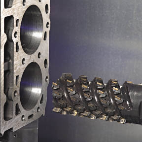
Courtesy of Makino
A prototype long-edge plunge milling cutter from Sandvik Coromant circular interpolates a cylinder bore in a CGI engine block.
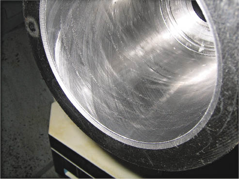
Courtesy of Makino
A honed CGI test cylinder illustrates the surface finish that can be achieved without handwork.
Table 1: Comparison of material properties.
| Gray iron (Class 30) | Compacted graphite iron (Grade 300) | Ductile iron (Grade 65-45-12) | |
|
Minimum tensile strength, KSI (MPa) |
30 (207) |
43.5 (300) |
65 (448) |
|
Minimum yield strength, KSI (MPa) |
-- |
30.5 (210) |
45 (310) |
|
Minimum elongation, percent |
0 |
1.5 |
12 |
|
Typical elastic modulus, psi in millions (GPa) |
16 to 18 (110 to 124) |
20 to 22 (138 to 152) |
23 to 25 (159 to 172) |
|
Typical hardness, HB |
187 to 241 |
143 to 207 |
156 to 217 |
|
Nodularity, percent |
0, flake |
20 to 30 maximum |
80 minimum |
Source: SAE International
As previously reported in Cutting Tool Engineering, Makino worked with Sandvik Coromant to develop a process and tooling that allows CGI cylinders to be finished at cycle times similar to those for gray cast iron ones. The cylinder bore is rough plunged with a CoroMill 210 high-feed facemill. Then, instead of applying a boring head, a special prototype long-edge plunge milling cutter tooled with indexable inserts finishes the bore via circular interpolation. The tool design allows the entire length of the bore to be cut in one helical revolution rather than having to make possibly 50 to 100 single helical passes, according to Makino.
“The inserts overlap perfectly so you don’t have one insert leaving a witness mark or telltale of its path,” Weidmer said. He added that the body of the long-edge plunge mill has milled pockets to hold ground inserts in a precise location, which reduces vibration and enables imparting a finer surface finish.
However, Weidmer noted that not all CNC machines are able to helically interpolate equally, a process that involves side load and can generate vibration. “The higher-end machining centers are much better at interpolating, or swinging, a circle and holding roundness,” he said. “Anytime you replace a boring tool with a helical milling process, the ability to hold roundness comes back to the accuracy of the machine, its control and its ability to make perfect circles.”
Weidmer added that helical interpolation requires communication between a machine’s servos and control to generate an accurate toolpath, especially when circular interpolating at a high feed rate. “To circular interpolate with a CNC machine, the two ballscrews [for the X and Y axes] must reverse direction every 90°,” he said, adding that a popular drawing toy functions as an analogy. “Similar to drawing a circle on an Etch A Sketch, you must reverse the direction of one of the knobs. The back and forth synchronization must be precise to make a perfect circle at high speeds.”
In addition, a rigid machine tool increases the accuracy of helical interpolation. “Added rigidity is a definite plus,” Weidmer said.
Iron Outlook
The “Iron Age” for many automotive components has passed, thanks to developments in alternative materials, such as aluminum, magnesium and high-strength and advanced high-strength steel. “Iron has come down and that’s just progress,” said Ducker Worldwide’s Schultz. “The iron guys have a struggle on their hands. If it weren’t for compacted graphite iron and high-torque engines in North America, all the engine blocks would go to aluminum.” He noted that a high-torque engine provides more than 500 newton-meters of torque.
In addition to large diesel engine blocks and cylinder heads, CeramTec’s Schneider indicated that CGI is sometimes used for making steering blocks for the hydraulics industry, and, as this issue’s cover shows, high-pressure oil pumps are another CGI application. Auto part manufacturers are also considering making CGI bed plates, exhaust manifolds, exhaust gas headers and rear axle boxes, according to Schneider.
Iron castings have applications outside of the automotive realm—from manhole covers to gigantic bases for wind turbines—but the advantages of CGI’s material properties for improving fuel economy have no bearing on parts that don’t travel.
When an end user does machine CGI, though, taking a machining system’s approach is critical. “All influences should be taken into account and never expect the same machining time, tool life and economic results [seen for other workpiece materials],” Schneider instructed. “Take your time to investigate everything before you start serial production, and choose the right tooling partner in advance. This investment will pay back.”
Although all machining elements are important when machining CGI, cutting tools lead the way. “When it comes to CGI, it’s the tooling that’s magic,” Weidmer said. “Unfortunately, there are not a lot of machine-specific technologies. It gets down to the tool design.” CTE
--------
About the Author: Alan Richter is editor of Cutting Tool Engineering, having joined the publication in 2000. Contact him at (847) 714-0175 or [email protected].
--------
Contributors
CeramTec North America Corp.
(615) 500-3996
www2.ceramtec.com
Ducker Worldwide
(800) 929-0086
www.ducker.com
Makino Inc.
(800) 552-3288
www.makino.com
Sandvik Coromant Co.
(800) 726-3845
www.coromant.sandvik.com/us
Related Glossary Terms
- Brinell hardness number ( HB)
Brinell hardness number ( HB)
Number related to the applied load (usually, 500 kgf and 3,000 kgf) and to the surface area of the permanent impression made by a 10mm ball indenter. The Brinell hardness number is a calculated value of the applied load (kgf) divided by the surface area of the indentation (mm2). Therefore, the unit of measure of a Brinell hardness number is kgf/mm2, but it is always omitted.
- abrasive
abrasive
Substance used for grinding, honing, lapping, superfinishing and polishing. Examples include garnet, emery, corundum, silicon carbide, cubic boron nitride and diamond in various grit sizes.
- boring
boring
Enlarging a hole that already has been drilled or cored. Generally, it is an operation of truing the previously drilled hole with a single-point, lathe-type tool. Boring is essentially internal turning, in that usually a single-point cutting tool forms the internal shape. Some tools are available with two cutting edges to balance cutting forces.
- boring head
boring head
Single- or multiple-point precision tool used to bring an existing hole within dimensional tolerance. The head attaches to a standard toolholder and a mechanism permits fine adjustments to be made to the head within a diameter range.
- centers
centers
Cone-shaped pins that support a workpiece by one or two ends during machining. The centers fit into holes drilled in the workpiece ends. Centers that turn with the workpiece are called “live” centers; those that do not are called “dead” centers.
- compacted graphite iron
compacted graphite iron
Cast iron having a graphite shape intermediate between the flake form typical of gray cast iron and the spherical form of fully spherulitic ductile cast iron. Also known as CG iron, CGI or vermicular iron, it is produced in a manner similar to that of ductile cast iron but using a technique that inhibits the formation of fully spherulitic graphite nodules.
- computer numerical control ( CNC)
computer numerical control ( CNC)
Microprocessor-based controller dedicated to a machine tool that permits the creation or modification of parts. Programmed numerical control activates the machine’s servos and spindle drives and controls the various machining operations. See DNC, direct numerical control; NC, numerical control.
- coolant
coolant
Fluid that reduces temperature buildup at the tool/workpiece interface during machining. Normally takes the form of a liquid such as soluble or chemical mixtures (semisynthetic, synthetic) but can be pressurized air or other gas. Because of water’s ability to absorb great quantities of heat, it is widely used as a coolant and vehicle for various cutting compounds, with the water-to-compound ratio varying with the machining task. See cutting fluid; semisynthetic cutting fluid; soluble-oil cutting fluid; synthetic cutting fluid.
- cutting speed
cutting speed
Tangential velocity on the surface of the tool or workpiece at the cutting interface. The formula for cutting speed (sfm) is tool diameter 5 0.26 5 spindle speed (rpm). The formula for feed per tooth (fpt) is table feed (ipm)/number of flutes/spindle speed (rpm). The formula for spindle speed (rpm) is cutting speed (sfm) 5 3.82/tool diameter. The formula for table feed (ipm) is feed per tooth (ftp) 5 number of tool flutes 5 spindle speed (rpm).
- elongation
elongation
In tensile testing, the increase in the gage length, measured after fracture of the specimen within the gage length, usually expressed as a percentage of the original gage length.
- facemill
facemill
Milling cutter for cutting flat surfaces.
- feed
feed
Rate of change of position of the tool as a whole, relative to the workpiece while cutting.
- gang cutting ( milling)
gang cutting ( milling)
Machining with several cutters mounted on a single arbor, generally for simultaneous cutting.
- hardness
hardness
Hardness is a measure of the resistance of a material to surface indentation or abrasion. There is no absolute scale for hardness. In order to express hardness quantitatively, each type of test has its own scale, which defines hardness. Indentation hardness obtained through static methods is measured by Brinell, Rockwell, Vickers and Knoop tests. Hardness without indentation is measured by a dynamic method, known as the Scleroscope test.
- interpolation
interpolation
Process of generating a sufficient number of positioning commands for the servomotors driving the machine tool so the path of the tool closely approximates the ideal path. See CNC, computer numerical control; NC, numerical control.
- milling
milling
Machining operation in which metal or other material is removed by applying power to a rotating cutter. In vertical milling, the cutting tool is mounted vertically on the spindle. In horizontal milling, the cutting tool is mounted horizontally, either directly on the spindle or on an arbor. Horizontal milling is further broken down into conventional milling, where the cutter rotates opposite the direction of feed, or “up” into the workpiece; and climb milling, where the cutter rotates in the direction of feed, or “down” into the workpiece. Milling operations include plane or surface milling, endmilling, facemilling, angle milling, form milling and profiling.
- milling cutter
milling cutter
Loosely, any milling tool. Horizontal cutters take the form of plain milling cutters, plain spiral-tooth cutters, helical cutters, side-milling cutters, staggered-tooth side-milling cutters, facemilling cutters, angular cutters, double-angle cutters, convex and concave form-milling cutters, straddle-sprocket cutters, spur-gear cutters, corner-rounding cutters and slitting saws. Vertical cutters use shank-mounted cutting tools, including endmills, T-slot cutters, Woodruff keyseat cutters and dovetail cutters; these may also be used on horizontal mills. See milling.
- milling machine ( mill)
milling machine ( mill)
Runs endmills and arbor-mounted milling cutters. Features include a head with a spindle that drives the cutters; a column, knee and table that provide motion in the three Cartesian axes; and a base that supports the components and houses the cutting-fluid pump and reservoir. The work is mounted on the table and fed into the rotating cutter or endmill to accomplish the milling steps; vertical milling machines also feed endmills into the work by means of a spindle-mounted quill. Models range from small manual machines to big bed-type and duplex mills. All take one of three basic forms: vertical, horizontal or convertible horizontal/vertical. Vertical machines may be knee-type (the table is mounted on a knee that can be elevated) or bed-type (the table is securely supported and only moves horizontally). In general, horizontal machines are bigger and more powerful, while vertical machines are lighter but more versatile and easier to set up and operate.
- physical vapor deposition ( PVD)
physical vapor deposition ( PVD)
Tool-coating process performed at low temperature (500° C), compared to chemical vapor deposition (1,000° C). Employs electric field to generate necessary heat for depositing coating on a tool’s surface. See CVD, chemical vapor deposition.
- plunge milling
plunge milling
Highly productive method of metal removal in which an axial machining operation is performed in a single tool sequence. The tool makes a series of overlapping, drill-like plunges to remove part of a cylindrical plug of material one after another. Because of the increased rigidity of a Z-axis move, the tool can cover a large cross-section of material.
- polycrystalline cubic boron nitride ( PCBN)
polycrystalline cubic boron nitride ( PCBN)
Cutting tool material consisting of polycrystalline cubic boron nitride with a metallic or ceramic binder. PCBN is available either as a tip brazed to a carbide insert carrier or as a solid insert. Primarily used for cutting hardened ferrous alloys.
- stiffness
stiffness
1. Ability of a material or part to resist elastic deflection. 2. The rate of stress with respect to strain; the greater the stress required to produce a given strain, the stiffer the material is said to be. See dynamic stiffness; static stiffness.
- tensile strength
tensile strength
In tensile testing, the ratio of maximum load to original cross-sectional area. Also called ultimate strength. Compare with yield strength.
- titanium nitride ( TiN)
titanium nitride ( TiN)
Added to titanium-carbide tooling to permit machining of hard metals at high speeds. Also used as a tool coating. See coated tools.
- tolerance
tolerance
Minimum and maximum amount a workpiece dimension is allowed to vary from a set standard and still be acceptable.
- toolpath( cutter path)
toolpath( cutter path)
2-D or 3-D path generated by program code or a CAM system and followed by tool when machining a part.
- turning
turning
Workpiece is held in a chuck, mounted on a face plate or secured between centers and rotated while a cutting tool, normally a single-point tool, is fed into it along its periphery or across its end or face. Takes the form of straight turning (cutting along the periphery of the workpiece); taper turning (creating a taper); step turning (turning different-size diameters on the same work); chamfering (beveling an edge or shoulder); facing (cutting on an end); turning threads (usually external but can be internal); roughing (high-volume metal removal); and finishing (final light cuts). Performed on lathes, turning centers, chucking machines, automatic screw machines and similar machines.
- wiper
wiper
Metal-removing edge on the face of a cutter that travels in a plane perpendicular to the axis. It is the edge that sweeps the machined surface. The flat should be as wide as the feed per revolution of the cutter. This allows any given insert to wipe the entire workpiece surface and impart a fine surface finish at a high feed rate.
- yield strength
yield strength
Stress at which a material exhibits a specified deviation from proportionality of stress and strain. An offset of 0.2 percent is used for many metals. Compare with tensile strength.
Author

Alan holds a bachelor’s degree in journalism from Southern Illinois University Carbondale. Including his 20 years at CTE, Alan has more than 30 years of trade journalism experience.