Machine shops go to great lengths to eliminate chatter.
Dan Maloney, one of the writers of the blog Hackaday (www.hackaday.com), even went so far as to modify the electronic drive unit on his engine lathe to automatically oscillate the spindle speed in hopes of breaking up vibration. Maloney’s approach—attaching a 555 timer board that drives a relay to toggle the IO pins on and off—was somewhat successful, but it’s not practical for CNC equipment.
Also, his statement that “vibration is a fact of life in almost every machining operation” is questionable. Perhaps he’s right, but if you can’t hear it, who cares?
Still, when chatter does rear its ugly head, something must be done. Before breaking out the soldering iron and a 555 timer, it’s a good idea to look at your cutting tools.
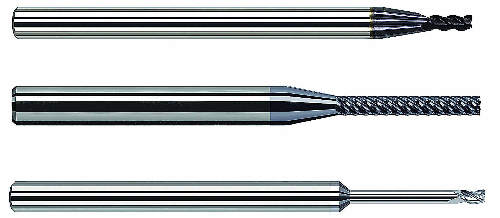
A sampling of the many variable-helix endmills available to manufacturers. Image courtesy of Harvey Performance.
Another blog, this one from Harvey Performance Co. LLC, Rowley, Mass., suggests that material-specific cutting tools are part of the answer.
For example, Chris Palmieri, production development engineer at Harvey Performance, said the geometry of an endmill designed for stainless steel differs from one used to machine aluminum. However, the same basic approach to chatter reduction applies in either instance—namely, varying the flute spacing and helix angles to break up the harmonics that lead to chatter.
“A variable-pitch tool assures that the time interval between two successive flutes contacting the material is never the same,” Palmieri said. “This actual amount of flute spacing is more a factor of endmill size rather than the material it’s designed for, however. A similar phenomenon occurs with variable-helix endmill geometry, where changing the angle slightly from flute to flute likewise serves to reduce chatter.”
Palmieri explained that, in either case, the geometry must also be based on the workpiece material—increasing the helix angle to allow for the aggressive feed rates used when cutting nonferrous metals, for instance. “That’s why it’s important to choose a cutter specifically designed for your machining application, especially where chatter is an issue.”
Palmieri said increased tool rigidity, tool balancing and minimal runout also contribute to chatter reduction. He recommends using a modified tool shank, like the Helical Solutions ToughGRIP shank. It offers a higher coefficient of friction, compared to a polished carbide shank, and eliminates any chance of movement within the holder.
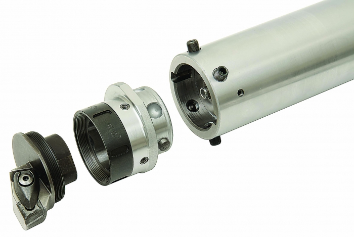
Seco Tools’ Steadyline dynamic-vibration-control tooling reportedly damps the harmonics that produce chatter, allowing a tool to be run at a higher feed rate. Image courtesy of Seco Tools.
It’s also important to consider the toolpath. “For harmonics to occur, cutting forces have to be in sync,” he said. “The spiral cutting paths used with trochoidal and other high-efficiency programming methods cause cutting forces to be exerted in different directions as the tool makes its way into and out of the workpiece. This does reduce vibration somewhat, but it’s still a good idea to use a variable-pitch, variable-helix tool to ensure that chatter is minimized as much as possible.”
Seco Tools LLC, Troy, Mich., refers to this type of chatter reduction as passive, in that proper machine construction, tool selection and, to a lesser extent, part design can go a long way toward eliminating chatter. When that’s not enough, dynamic vibration control must be applied.
That’s according to a recent white paper by Seco Product Manager Pierre Zunino and R&D Engineer Yannick Groll. In it, the two state that a “pretuned vibration damper consisting of a heavy-metal mass suspended inside the toolholder bar” enables long-overhang operations to be performed at least twice as fast as those using nondamped toolholders, with better part finish and tool life to boot.
In one example, Seco engineers tested the effectiveness of dynamic-vibration-control toolholders when side milling. Using one of the company’s nondamped Combimaster holders, they machined CK50 high-carbon steel with a 0.787"-dia. (20mm) endmill spinning at about 5,000 rpm (a cutting speed of 1,023 sfm, or 312 m/min.), a feed rate of 0.118 ipt (0.3 mm/tooth) and a 0.035" (0.9mm) DOC.
When the same test was performed using Seco’s Steadyline system, it was possible to “increase cutting depth by 2.3 times, to 0.087", without unwanted vibration,” the authors wrote.
Similar results were obtained when boring 42CrMo4 chrome-moly steel, where the boring time was reduced from 12 to just 2 hours, more than an 80 percent reduction. The study further recommends that damped bars be mounted directly to the machine without intermediary extensions or reductions and that a dual-contact mounting system, such as Capto, be used for optimal results. In some cases, an increased feed rate may be needed to “trigger” the device’s damping effect.
Contact Details

Related Glossary Terms
- boring
boring
Enlarging a hole that already has been drilled or cored. Generally, it is an operation of truing the previously drilled hole with a single-point, lathe-type tool. Boring is essentially internal turning, in that usually a single-point cutting tool forms the internal shape. Some tools are available with two cutting edges to balance cutting forces.
- chatter
chatter
Condition of vibration involving the machine, workpiece and cutting tool. Once this condition arises, it is often self-sustaining until the problem is corrected. Chatter can be identified when lines or grooves appear at regular intervals in the workpiece. These lines or grooves are caused by the teeth of the cutter as they vibrate in and out of the workpiece and their spacing depends on the frequency of vibration.
- computer numerical control ( CNC)
computer numerical control ( CNC)
Microprocessor-based controller dedicated to a machine tool that permits the creation or modification of parts. Programmed numerical control activates the machine’s servos and spindle drives and controls the various machining operations. See DNC, direct numerical control; NC, numerical control.
- cutting speed
cutting speed
Tangential velocity on the surface of the tool or workpiece at the cutting interface. The formula for cutting speed (sfm) is tool diameter 5 0.26 5 spindle speed (rpm). The formula for feed per tooth (fpt) is table feed (ipm)/number of flutes/spindle speed (rpm). The formula for spindle speed (rpm) is cutting speed (sfm) 5 3.82/tool diameter. The formula for table feed (ipm) is feed per tooth (ftp) 5 number of tool flutes 5 spindle speed (rpm).
- endmill
endmill
Milling cutter held by its shank that cuts on its periphery and, if so configured, on its free end. Takes a variety of shapes (single- and double-end, roughing, ballnose and cup-end) and sizes (stub, medium, long and extra-long). Also comes with differing numbers of flutes.
- feed
feed
Rate of change of position of the tool as a whole, relative to the workpiece while cutting.
- flutes
flutes
Grooves and spaces in the body of a tool that permit chip removal from, and cutting-fluid application to, the point of cut.
- gang cutting ( milling)
gang cutting ( milling)
Machining with several cutters mounted on a single arbor, generally for simultaneous cutting.
- helix angle
helix angle
Angle that the tool’s leading edge makes with the plane of its centerline.
- inches per tooth ( ipt)
inches per tooth ( ipt)
Linear distance traveled by the cutter during the engagement of one tooth. Although the milling cutter is a multi-edge tool, it is the capacity of each individual cutting edge that sets the limit of the tool, defined as: ipt = ipm/number of effective teeth 5 rpm or ipt = ipr/number of effective teeth. Sometimes referred to as the chip load.
- lathe
lathe
Turning machine capable of sawing, milling, grinding, gear-cutting, drilling, reaming, boring, threading, facing, chamfering, grooving, knurling, spinning, parting, necking, taper-cutting, and cam- and eccentric-cutting, as well as step- and straight-turning. Comes in a variety of forms, ranging from manual to semiautomatic to fully automatic, with major types being engine lathes, turning and contouring lathes, turret lathes and numerical-control lathes. The engine lathe consists of a headstock and spindle, tailstock, bed, carriage (complete with apron) and cross slides. Features include gear- (speed) and feed-selector levers, toolpost, compound rest, lead screw and reversing lead screw, threading dial and rapid-traverse lever. Special lathe types include through-the-spindle, camshaft and crankshaft, brake drum and rotor, spinning and gun-barrel machines. Toolroom and bench lathes are used for precision work; the former for tool-and-die work and similar tasks, the latter for small workpieces (instruments, watches), normally without a power feed. Models are typically designated according to their “swing,” or the largest-diameter workpiece that can be rotated; bed length, or the distance between centers; and horsepower generated. See turning machine.
- milling
milling
Machining operation in which metal or other material is removed by applying power to a rotating cutter. In vertical milling, the cutting tool is mounted vertically on the spindle. In horizontal milling, the cutting tool is mounted horizontally, either directly on the spindle or on an arbor. Horizontal milling is further broken down into conventional milling, where the cutter rotates opposite the direction of feed, or “up” into the workpiece; and climb milling, where the cutter rotates in the direction of feed, or “down” into the workpiece. Milling operations include plane or surface milling, endmilling, facemilling, angle milling, form milling and profiling.
- shank
shank
Main body of a tool; the portion of a drill or similar end-held tool that fits into a collet, chuck or similar mounting device.
- toolholder
toolholder
Secures a cutting tool during a machining operation. Basic types include block, cartridge, chuck, collet, fixed, modular, quick-change and rotating.
- toolpath( cutter path)
toolpath( cutter path)
2-D or 3-D path generated by program code or a CAM system and followed by tool when machining a part.
Author

Kip Hanson is a contributing editor for Cutting Tool Engineering magazine. Contact him by phone at (520) 548-7328 or via e-mail at [email protected].