There’s a long-running argument in the machining community: Should I tap or should I thread-mill?
For many, the former is the preferred method of threadmaking on a CNC machining center. It’s fast, easy to program and can even be done offline—on a drill press or with a tapping arm—if the CNC machine is better utilized another way.
Yet others contend that thread milling is more accurate and almost as fast. Plus, there’s no risk of the tap breaking inside the workpiece, which often results in scrapping the part.
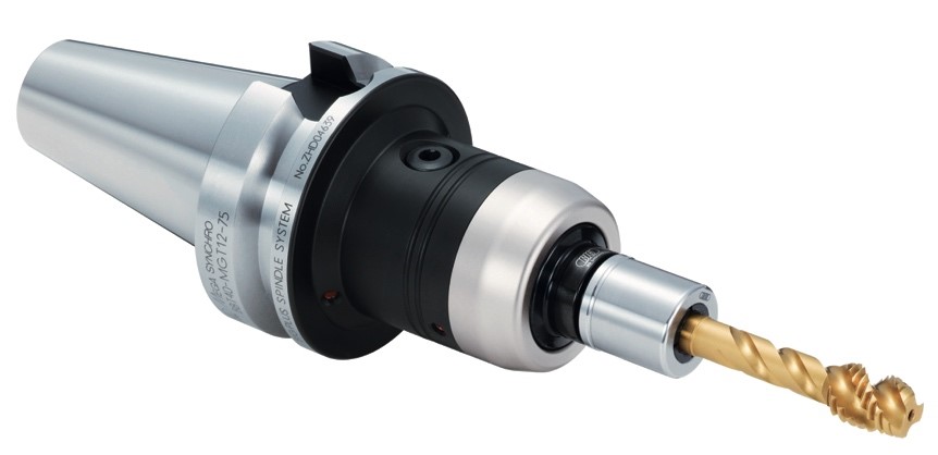
BIG KAISER’s MEGA Synchro drives taps securely and compensates for the small synchronization errors common with many CNC machine tools. Image courtesy of BIG KAISER Precision Tooling.
Which group is right? The answer depends on several factors.
As a rule, thread mills are limited to threads no smaller than 1⁄8"(3.175mm), and because of the high cutting forces and resulting tool deflection, are generally limited to threading holes about 3 diameters deep. On the other hand, taps for #000-120 watch threads are readily available, and an extension tap can reach roughly 20 diameters deep.
Taps suitable for threading a fire hydrant hose are also available, but good luck driving a tool that big. Most CNC machine spindles struggle with tap diameters 1⁄2" (12.7mm) and larger.
When tapping, there’s no way to adjust the thread’s pitch diameter except by changing to a different “H” size tap. This requires machine downtime and a large tool inventory. When thread milling, size adjustment is a simple offset. What’s more, the thread mill you applied on the 1⁄4"-20 job last week can be used on the 9⁄16"-20 job today, or any other 20-pitch thread that comes along.
Regardless of the workpiece material and preferred threading method, what’s most important is that the job is tooled and programmed properly. Here’s a list of pointers to help you do that:
- With synchronous, or rigid, tapping, avoid using ER or comparable collet-style toolholders. A number of tooling suppliers offer holders that grip and drive the tap more securely than a collet. These holders also provide a small amount of axial “float” to compensate for the spindle-to-Z-axis synchronization errors common with many CNC machine tools. On a related note, thread mills should be gripped like any other milling cutter: with a well-maintained milling chuck or shrink-fit holder.
- Some older machining centers don’t have rigid tapping capabilities. For these, a tension-compression holder is a must. Be sure to keep the spindle speed sufficiently low—no more than 500 rpm—so that it can reverse before the toolholder runs out of axial travel. Doing this will prevent breaking the drive pin inside. Here again, several companies provide tap holders equipped with quick-change tap adapters and internal clutch mechanisms that minimize the chance of damaging the holder.
- A self-reversing tapping head may require installation of a drive dog on the machine’s spindle face, but it can be adapted to almost any machining center. Depending on its size, this type of attachment allows tapping at up to several thousand rpm and avoids the wear and tear that comes with repetitive spindle reversal. If you tap a lot of holes in aluminum, brass and other relatively soft materials, this method blows the doors off thread milling and traditional tapping methods.
- If you’re unsure about the programming part of all this, you’re in luck. Several tool supplier websites have G-code calculators to generate the necessary toolpaths for thread milling. (Most CAM systems are capable of this as well.) When rigid tapping, use whatever M code is specified in the machine’s programming manual. Be sure to use a G84 or comparable tapping cycle—don’t use a G01 or G81 command, unless you enjoy breaking taps.
- Don’t forget that much of what was discussed here applies equally to mill-turn centers and multitask lathes, which, thanks to their C-axis capabilities, can thread-mill with ease. These, as well as many 2-axis lathes, also offer rigid tapping—again, be sure to use the correct toolholder for the application.
What about hard materials such as heat-treated 17-4 PH or D2 tool steel? There’s little chance of successfully thread milling metals much above 45 HRC. And if you’re going to try to tap them, be prepared to duck the flying shrapnel when the tap explodes! Internal thread grinding and, on rare occasion, orbiting sinker EDMing are about the only ways to produce good threads in materials harder than 45 HRC.
Contact Details

Related Glossary Terms
- centers
centers
Cone-shaped pins that support a workpiece by one or two ends during machining. The centers fit into holes drilled in the workpiece ends. Centers that turn with the workpiece are called “live” centers; those that do not are called “dead” centers.
- chuck
chuck
Workholding device that affixes to a mill, lathe or drill-press spindle. It holds a tool or workpiece by one end, allowing it to be rotated. May also be fitted to the machine table to hold a workpiece. Two or more adjustable jaws actually hold the tool or part. May be actuated manually, pneumatically, hydraulically or electrically. See collet.
- collet
collet
Flexible-sided device that secures a tool or workpiece. Similar in function to a chuck, but can accommodate only a narrow size range. Typically provides greater gripping force and precision than a chuck. See chuck.
- computer numerical control ( CNC)
computer numerical control ( CNC)
Microprocessor-based controller dedicated to a machine tool that permits the creation or modification of parts. Programmed numerical control activates the machine’s servos and spindle drives and controls the various machining operations. See DNC, direct numerical control; NC, numerical control.
- computer-aided manufacturing ( CAM)
computer-aided manufacturing ( CAM)
Use of computers to control machining and manufacturing processes.
- drilling machine ( drill press)
drilling machine ( drill press)
Machine designed to rotate end-cutting tools. Can also be used for reaming, tapping, countersinking, counterboring, spotfacing and boring.
- gang cutting ( milling)
gang cutting ( milling)
Machining with several cutters mounted on a single arbor, generally for simultaneous cutting.
- grinding
grinding
Machining operation in which material is removed from the workpiece by a powered abrasive wheel, stone, belt, paste, sheet, compound, slurry, etc. Takes various forms: surface grinding (creates flat and/or squared surfaces); cylindrical grinding (for external cylindrical and tapered shapes, fillets, undercuts, etc.); centerless grinding; chamfering; thread and form grinding; tool and cutter grinding; offhand grinding; lapping and polishing (grinding with extremely fine grits to create ultrasmooth surfaces); honing; and disc grinding.
- machining center
machining center
CNC machine tool capable of drilling, reaming, tapping, milling and boring. Normally comes with an automatic toolchanger. See automatic toolchanger.
- milling
milling
Machining operation in which metal or other material is removed by applying power to a rotating cutter. In vertical milling, the cutting tool is mounted vertically on the spindle. In horizontal milling, the cutting tool is mounted horizontally, either directly on the spindle or on an arbor. Horizontal milling is further broken down into conventional milling, where the cutter rotates opposite the direction of feed, or “up” into the workpiece; and climb milling, where the cutter rotates in the direction of feed, or “down” into the workpiece. Milling operations include plane or surface milling, endmilling, facemilling, angle milling, form milling and profiling.
- milling machine ( mill)
milling machine ( mill)
Runs endmills and arbor-mounted milling cutters. Features include a head with a spindle that drives the cutters; a column, knee and table that provide motion in the three Cartesian axes; and a base that supports the components and houses the cutting-fluid pump and reservoir. The work is mounted on the table and fed into the rotating cutter or endmill to accomplish the milling steps; vertical milling machines also feed endmills into the work by means of a spindle-mounted quill. Models range from small manual machines to big bed-type and duplex mills. All take one of three basic forms: vertical, horizontal or convertible horizontal/vertical. Vertical machines may be knee-type (the table is mounted on a knee that can be elevated) or bed-type (the table is securely supported and only moves horizontally). In general, horizontal machines are bigger and more powerful, while vertical machines are lighter but more versatile and easier to set up and operate.
- pitch
pitch
1. On a saw blade, the number of teeth per inch. 2. In threading, the number of threads per inch.
- tap
tap
Cylindrical tool that cuts internal threads and has flutes to remove chips and carry tapping fluid to the point of cut. Normally used on a drill press or tapping machine but also may be operated manually. See tapping.
- tapping
tapping
Machining operation in which a tap, with teeth on its periphery, cuts internal threads in a predrilled hole having a smaller diameter than the tap diameter. Threads are formed by a combined rotary and axial-relative motion between tap and workpiece. See tap.
- threading
threading
Process of both external (e.g., thread milling) and internal (e.g., tapping, thread milling) cutting, turning and rolling of threads into particular material. Standardized specifications are available to determine the desired results of the threading process. Numerous thread-series designations are written for specific applications. Threading often is performed on a lathe. Specifications such as thread height are critical in determining the strength of the threads. The material used is taken into consideration in determining the expected results of any particular application for that threaded piece. In external threading, a calculated depth is required as well as a particular angle to the cut. To perform internal threading, the exact diameter to bore the hole is critical before threading. The threads are distinguished from one another by the amount of tolerance and/or allowance that is specified. See turning.
- toolholder
toolholder
Secures a cutting tool during a machining operation. Basic types include block, cartridge, chuck, collet, fixed, modular, quick-change and rotating.
Author

Kip Hanson is a contributing editor for Cutting Tool Engineering magazine. Contact him by phone at (520) 548-7328 or via e-mail at [email protected].