This article shows a setup method for cutting long, tapered surfaces on a three-axis milling machine. The part to be made is 533.4 mm (21") long by 101.6 mm (4") wide by 50.8 mm (2") thick. It has a 0.3-degree taper in the length dimension and a 4.3-degree taper in the width dimension. There are also threaded holes perpendicular to each tapered surface.
I find it convenient when cutting a long part on a milling machine to hold the part with two milling vises. Figure 1 shows the finished part set on two vises. The surface parallel to the machine table with the threaded holes has the 0.3-degree taper with 13 5/16-18 holes perpendicular to the tapered surface.
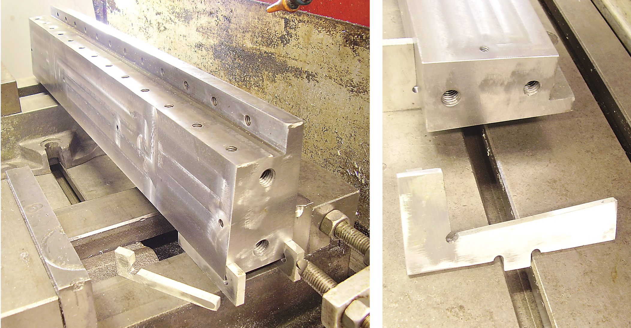
The finished part is shown set on two vises (left). The finished part is displayed on the setup with the angle blocks used to set the 4.3-degree angle (right). Image courtesy of B. Taylor
So the question is how to accurately set the taper. What I do is make L-shaped angle blocks to fit between the vise bed and the part with the short leg of the L against the end of the part. One of those blocks is shown on a vise bed beside the part. The angle blocks are CNC-routed from 6.35 mm (0.25") thick aluminum plate. The taper amounts to 2.794 mm (0.11") in the 533.4 mm long part. The inside surfaces of the L are at right angles to each other and tapered at 0.3 degree from the outside surfaces. When the short leg of the L is against the end of the part, the correct angle is ensured. It gives visual assurance to an operator that the angle being cut is proper. Let a CNC tool make the angle, and the work of the machine operator is simplified.
Note the work stop against one of the angle blocks. This is a little more insurance that the setup is correct. You want a rigid, positive setup so the machine aggressively can cut the metal. That’s one way that the setup time pays off.
Figure 2 shows the finished part on the setup with the angle blocks used to set the 4.3-degree angle. Three angle blocks are used here. Because of the relation of the taper to the other surfaces, holding the part with vises is not appropriate. Notice the tab on the bottom of the angle block. That tab fits into the T-slots in the machine table. This speeds up setup since the y-axis position of an angle block is set by the tab being inserted into a T-slot. When the part is placed on the three angle blocks, the y-axis position is set and the x-axis surfaces of the part are parallel to the x-axis of the machine tool. The part is held by a T-slot clamp in the usual way.
Figure 3 shows the three different angle blocks used. This way of setting angles allows a more rigid setup than using a tilting table, tilting vise or sine plate. A more rigid setup means faster metal removal and better surface finish. I find that the time spent making the angle blocks makes this type of job easier than fiddling around with gauge blocks to set angles.
All in all, it’s a timesaver.
Related Glossary Terms
- computer numerical control ( CNC)
computer numerical control ( CNC)
Microprocessor-based controller dedicated to a machine tool that permits the creation or modification of parts. Programmed numerical control activates the machine’s servos and spindle drives and controls the various machining operations. See DNC, direct numerical control; NC, numerical control.
- gang cutting ( milling)
gang cutting ( milling)
Machining with several cutters mounted on a single arbor, generally for simultaneous cutting.
- milling
milling
Machining operation in which metal or other material is removed by applying power to a rotating cutter. In vertical milling, the cutting tool is mounted vertically on the spindle. In horizontal milling, the cutting tool is mounted horizontally, either directly on the spindle or on an arbor. Horizontal milling is further broken down into conventional milling, where the cutter rotates opposite the direction of feed, or “up” into the workpiece; and climb milling, where the cutter rotates in the direction of feed, or “down” into the workpiece. Milling operations include plane or surface milling, endmilling, facemilling, angle milling, form milling and profiling.
- milling machine ( mill)
milling machine ( mill)
Runs endmills and arbor-mounted milling cutters. Features include a head with a spindle that drives the cutters; a column, knee and table that provide motion in the three Cartesian axes; and a base that supports the components and houses the cutting-fluid pump and reservoir. The work is mounted on the table and fed into the rotating cutter or endmill to accomplish the milling steps; vertical milling machines also feed endmills into the work by means of a spindle-mounted quill. Models range from small manual machines to big bed-type and duplex mills. All take one of three basic forms: vertical, horizontal or convertible horizontal/vertical. Vertical machines may be knee-type (the table is mounted on a knee that can be elevated) or bed-type (the table is securely supported and only moves horizontally). In general, horizontal machines are bigger and more powerful, while vertical machines are lighter but more versatile and easier to set up and operate.
- parallel
parallel
Strip or block of precision-ground stock used to elevate a workpiece, while keeping it parallel to the worktable, to prevent cutter/table contact.
Author

Brandt Taylor is owner of Berlin, Massachusetts-based Taylor Engineering, a machine shop.