Countersinking Aircraft Materials
This article traces the changes in countersink design and materials that have been made to satisfy the demands of the aerospace industry.
| The aircraft industry’s increased use of titanium and abrasive composites has led to the development of a new generation of countersinks. |
Aircraft manufacturers’ primary skill is the ability to fasten two pieces of material together in such a way that they don’t fly apart at Mach 3 in a 90° turn. This requires precision hole preparation prior to the insertion of the fastener – specifically, countersinking.
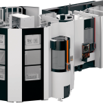
In the late 1930s, the microstop cage unit was developed. A threaded-shank countersink is screwed into the unit, which is driven by a hand-held drill motor and allows the mechanic to adjust the depth of the countersink in 0.001″ increments with good accuracy and repeatability. The basic design of the microstop units has not changed much in the last 60 years. Today’s microstop units are, however, much sturdier and more accurate, incorporating improved bearing technology to achieve the higher rpm rates required for today’s exotic materials (Figure 1).
Aircraft manufacturers are interested in improved versions of these manually operated tools, despite the automation of their processes. Automated fastening is increasing in use as machines are developed with the capability of processing larger panels. For example, a wing may be assembled on a very large Gem-Cor machine, a large jig upon which the wing is set. A preprogrammed robot drills and countersinks the hole in one operation using a combination drill/countersink (the robot also inserts the fastener and shaves the fastener head if required).
However, the vast majority of hole countersinking is still done in a separate operation utilizing hand-held microstop cage units, because building a machine big enough to handle large airplane parts is impractical in most cases.
 |
Figure 1: A microstop cage unit used for hand-held countersinking operations. |
New Materials, New Tools
In the past, airplanes were constructed primarily of aluminum. HSS countersinks of a 2- or 3-flute configuration were the industry standard. With the advent of titanium and other tough and abrasive materials, 2- and 3-flute carbide tools began to make inroads into the industry. The composite materials of today are even more abrasive and require the use of polycrystalline-diamond (PCD) cutting edges.
Threaded countersinks come with either removable or integral pilots. The integral-pilot style (Figure 2) predominates, because it has a controlled fillet radius at the intersection of the angle and the pilot, which is generally favored by the aircraft industry for countersinking. This design eliminates the sharp corner, which is a stress point on the tool. The radius is ground at the same time the pilot is ground to ensure tangency.
In most cases, if such a radius were ground into a removable-pilot tool, the user could employ only one size of pilot for that tool. This eliminates the chief advantage of a removable-pilot tool – to allow the use of many different pilots so that a separate countersink isn’t needed for each hole size. And if the pilot did not line up correctly because of runout in the hole or pilot shank, the user might score the hole or end up with a partial radius in the workpiece.
 |
Figure 2: An integral-pilot carbide countersink. |
The carbide version of the integral-pilot tool is manufactured in two ways: carbide tipped, in which the cutting edges are carbide and the pilot is HSS; or solid carbide, in which the entire front end of the tool is carbide. The carbide-tipped tool is less expensive but has a shorter tool life than the solid tool, due to the wear on the HSS pilot. The more abrasive the workpiece material is, the shorter the tool life. The solid-carbide tool is superior if one considers cost per hole rather than cost per tool.
Coping With Composites
The increased use of composite materials in the aircraft industry has changed the type and configuration of countersinks used today. The primary change has been higher degrees of clearance – 16° to 20° primary on a PCD tool as compared to 6° to 10° on a carbide tool for titanium or 3° to 4° on an HSS tool for steel. Tools designed to cut Kevlar® additionally have a sweeping hooked flute combined with a high clearance angle.
For composites, PCD is the optimal tool material. In composite-material applications, HSS usually doesn’t work at all due to highly accelerated tool wear. Carbide will work, but with greatly reduced tool life compared to its performance in titanium. Nevertheless, it is sometimes necessary to use carbide rather than PCD when a certain geometry required on the cutting tool cannot be achieved with PCD blanks – for example, a drillpoint or a radically hooked face for a more burr-free countersink in Kevlar. See Table 1 for recommended cutting tool materials for various workpiece materials.
PCD cannot be used in ferrous materials. Because it is carbon-based, under heat it will become one with the workpiece. Thus it is limited to nonferrous and composite applications. Ferrous machining requires carbide or HSS tools.
|
||||||||||||||||||||||||||||||||
|
Table 1: Tool-material recommendations for various aircraft materials. |
||||||||||||||||||||||||||||||||
Coolant should not be applied when countersinking composites using PCD tools. Coolant has a tendency to react with the composite and cause delamination. And it isn’t really necessary, because PCD has very good heat-transfer characteristics. When using carbide on composites, a cold-air spray may help.
 |
Figure 3: A radiused PCD countersink with replaceable blades and pilots. |
PCD Shapes Up
One of the problems shops face when working with PCD is the limited ability to grind certain tool geometries. But Craig Tools Inc., El Segundo, CA, has developed a tool that addresses this problem—the Versi-Sink, a replaceable-blade, removable-pilot, threaded-shank countersink (Figure 3). Unlike other PCD countersinks, the replaceable-blade tool has a controlled fillet radius. Normally, this filleted radius is difficult to achieve on a PCD countersink, especially in a 2-flute configuration, without causing lip-height variation. Craig accomplished this by grinding the blades separately on a specially jigged machine and then mechanically holding the blades in the body. The Versi-Sink accepts replaceable blades that have the controlled radius or replaceable straight blades for use when the radius is not required. The tool can be used in a 1- or 2-flute configuration. The pilot also is replaceable, so that as it wears out or the hole size to be machined changes, a new pilot can be installed and the same set of blades used. The radius will remain tangent to the pilot diameter as the insert locates on a ground flat on the pilot shank and can be set by the mechanic without the use of an optical comparator. This provides more versatility than the traditional removable-pilot countersink.
A brazed-tip, 2-flute, nonradiused PCD countersink can be used when the fillet radius is not required (Figure 4). The 2-flute design is generally preferable to 1- or 3-flute designs. Balance and cutting action is superior as long as the tool has good lip height. If one flute protrudes too much, then chatter and egg-shaped holes will result. In the past, this problem was more prevalent, so users opted for 1-flute PCD countersinks to avoid this problem and to minimize the diamond cost.
 |
Figure 4: A nonradiused PCD countersink with replaceable blades and pilots. |
The 2-flute brazed PCD countersink is easy to recondition, provided the user has the right equipment. These tools, like all PCD tools, have very high clearance angles that must be maintained when the tool is reground to prevent a drastic reduction in performance. This problem often occurs when a user attempts to service these tools in-house. PCD is extremely difficult to grind on a standard tool-and-cutter grinder. In attempting to just clean up the cutting edge, the operator may reduce the amount of clearance by removing less material to make the job easier. This practice effectively reduces the clearance at the cutting edge. Therefore, it is usually much more cost-effective to send the tool back to the manufacturer for reconditioning.
Cost Per Hole
The following is a cost-per-hole comparison of a graphite-epoxy-laminate application:
| HSS cutter | 30 to 50 holes |
| Carbide-tipped cutter | 300 to 500 holes |
| PCD-tipped cutter with fillet radius | 5000 to 10,000 holes |
| HSS cutter @ $5 each, no resharpening | $5/50 holes=$0.10/hole |
| Carbide cutter @ $28 each, two resharpenings @ $8.35 each ot $16.70 reconditioning cost | $44.70/1500 holes=$0.03/hole |
| PCD-insert cutter with fillet radius @ $39.45 each, 10 pilots @ $19.85 each or $198.50, insert set @ $220.75 each, three resharpenings @ $83.75 or $251.25 reconditioning cost. | $709.95/40,000 holes = $0.0177/hole |
The HSS, integral-pilot, threaded-shank countersink probably will never be phased out completely, but there is a definite trend toward more carbide and PCD tools. The sticker shock of PCD is slowly fading as the cost-per-hole savings becomes more widely recognized. Many companies have seen their perishable-tooling costs increase dramatically as they purchase more and more carbide tools to meet the demands of their shops and get fewer and fewer holes per tool due to increased composite-material applications. The PCD tool then becomes much more attractive as a means to reducing costs and increasing productivity through greatly reduced tool changes and a radically higher number of holes per tool.
The cutting tool industry can look forward to increased use of composites in all areas of manufacturing. In the aircraft industry, this means a continuing shift toward carbide, PCD, and coated tools. Cost per hole will always be the deciding factor in cutting tool selection.
About the Author
William Cleveland is president of Craig Tools Inc., El Segundo, CA. He also serves as president of the United States Cutting Tool Institute, Cleveland.
Related Reading
- Related guide: Countersink Resources.


MFGAxis Discussion