Indexable insert tools enable manufacturers to machine parts with carbide and other hard materials without having to purchase a solid cutting tool made of the same material as the cutting edges — a progressively expensive proposition as tool diameter increases.
Tools and techniques, however, are available to further reduce production costs and the cost per cutting edge when using indexable inserts. This article covers double-sided inserts and high-feed indexable insert milling tools.
On the Double
Double-sided inserts have a long history in metalcutting of reducing the cost per cutting edge, but cutting tool manufacturers continue to refine them and introduce offerings. Vernon Hills, Illinois-based YG-1 Tool (USA) Co., for example, announced that its new ENMX09 double-sided inserts have a total of four cutting edges and are suitable for high-feed milling.
“What makes them unique is the thickness, which addresses one of the major issues you have with double-sided, high-feed inserts,” said Jan Andersson, director of product management for indexable inserts. “The nature of the application is that you will always have flank wear on the bottom of the insert.”
He said the ENMX09 is 6.2 mm (0.244") thick, which compares with insert thicknesses of 4.6 mm (0.181") and 4.8 mm (0.189") for two popular competing products.
Studies by YG-1 Tool (USA) showed that end users either used only one side of a double-sided, high-feed insert or accepted that they would obtain only 60% to 80% of the tool life for the second side compared with the first side when they used both sides, Andersson said.
“Making a thicker insert allowed us to accept that flank wear but without having the encroachment issue,” he said. “This means four true cutting edges.”
Developments in production technology have enabled tool manufacturers to increase the capability of double-sided inserts. Arlington, Texas-based Iscar USA, for instance, employs pressing technology with multiple stamping heads to increase the complexity of its double-sided inserts, said Keith Carlile, national product specialist for milling, who’s based in Centralia, Washington.
“We can now make an insert that we could only dream about in the past,” he said.
Carlile said one benefit is an increase in the cross-sectional thickness of the insert to permit more aggressive cutting than past products and provide adequate space for including Iscar’s signature dovetail clamping configuration on the top of the insert. The dovetail traps the insert rigidly in the pocket and takes pressure off the screw, he said.
“It completely eliminates that micro back lift we have on the opposite side of the business end,” he said.
In addition, Carlile said the dovetail design enables the toolmaker to manipulate how the insert sits in the pocket.
“For instance,” he said, “we can lay an insert negatively in the pocket with an additional dovetail to make a very strong, robust mount but still have enough carbide so that we can bring the cutting edge positive and have a positive clearance underneath.”
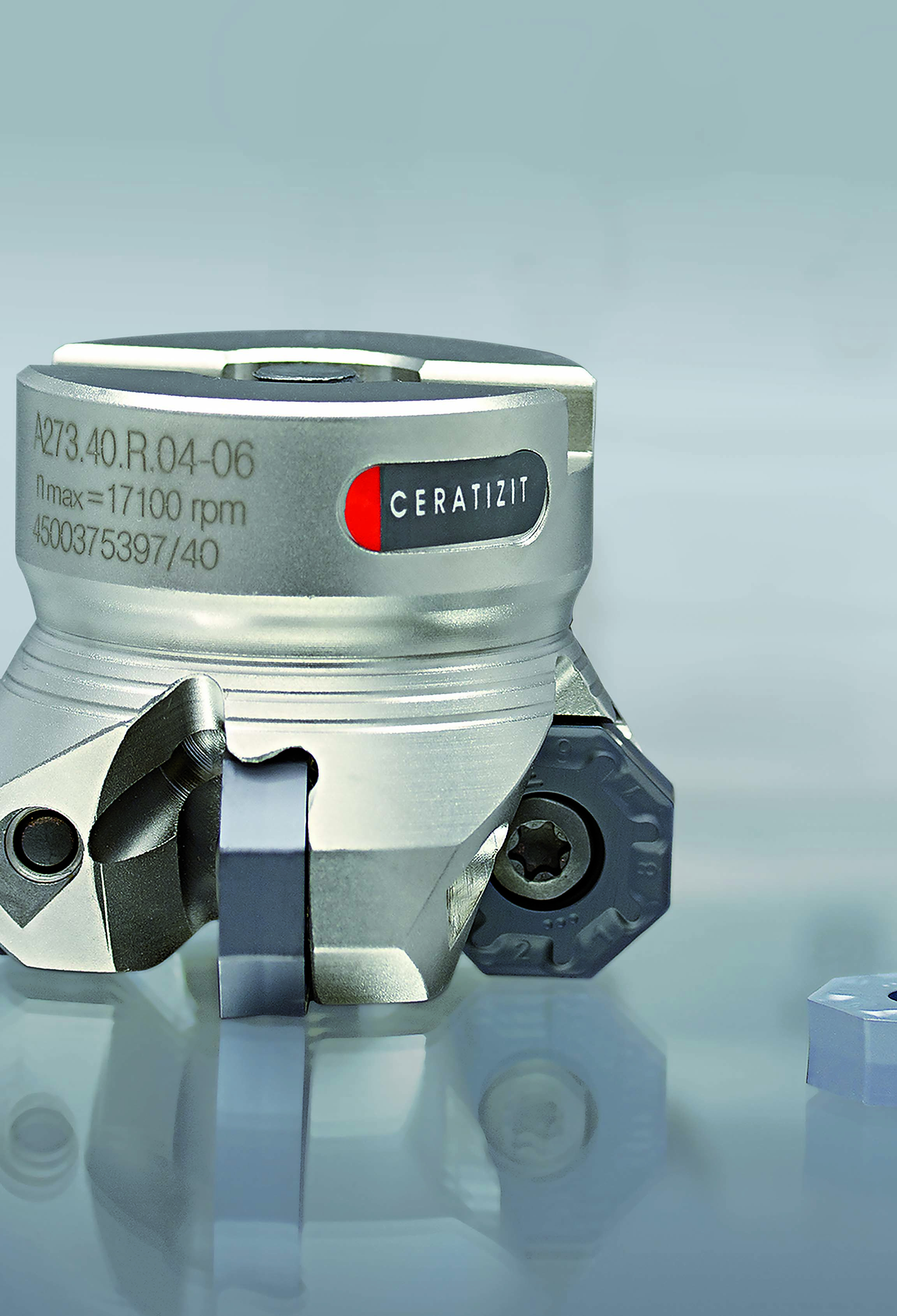
Robert Bokram, product manager for cutting tools at Ceratizit USA Inc. in Warren, Michigan, said toolmakers can offer double-sided milling inserts that have negative clearance geometries and high-positive rake angles.
“The ‘pos/neg’ pocket orientation allows for insert designs that double the number of cutting edges per insert, utilizing higher rake angle chipbreaker geometries to compensate for the negative pocket orientation,” he said. “These more robust designs have proven to be very soft cutting, demonstrating similar spindle torque values to the conventional ‘pos/pos’ milling cutter designs.”
Bokram said the more robust geometry permits the double-sided inserts to have an expanded range of applications beyond finishing, including medium and roughing operations, as well as machining heat-resistant superalloys and titanium.
“They can handle heavier depths of cut and higher feed rates than conventional positive designs due to better support in the pocket,” he said.
An Abundance of Edges
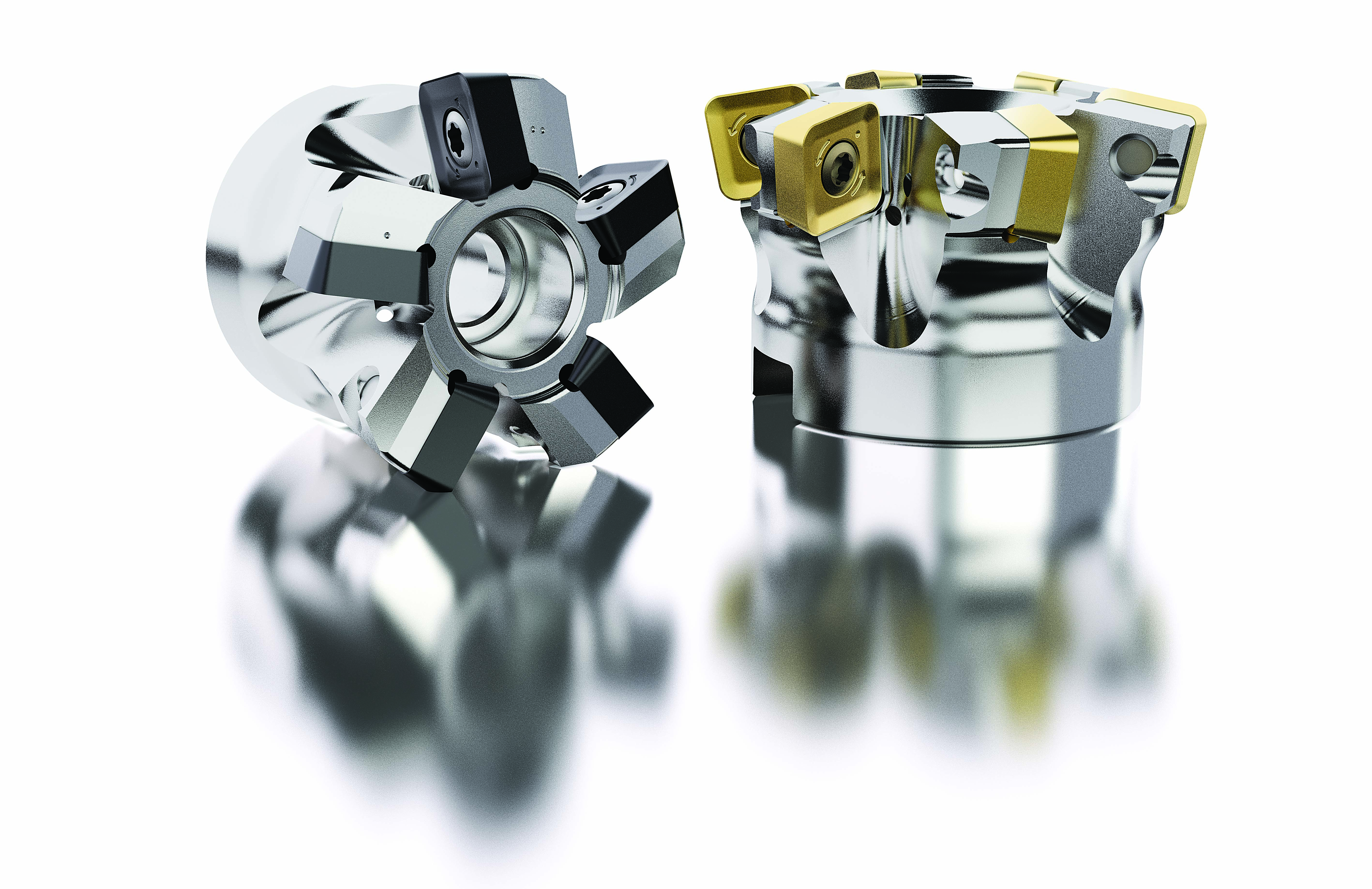
David Romlin, corporate product manager for indexable milling tools at Seco Tools AB in Fagersta, Sweden, said a time-tested double-sided insert is the Double Octomill, which has eight cutting edges per side for facemilling operations. (Seco Tools LLC is in Troy, Michigan.) A more recent development is the Double Turbo square shoulder mills that accept inserts with four cutting edges, which have an 11-degree positive helix angle to reduce power consumption.
“That provides good economy to the customer with the double-sided technology,” he said.
In addition to square inserts with eight cutting edges and octagon inserts with 16 edges, Carlile said Iscar offers the H606 double-sided round insert with six total edges. The insert gives adequate room for a helix angle on the outer diameter to supply a shearing rather than a pounding cutting action. He said an undercut feature on the bottom of the insert bisects a chip and reduces the amount of force it takes to remove the chip.
“We couldn’t do that with a single-sided insert,” he said. “We would have to have a very thick insert.”
However, limitations exist for inserts with edges on both sides. For example, Romlin said there’s a trade-off in productivity for double-sided inserts because the number of teeth in the cutter is slightly lower than for single-sided inserts.
“The double-sided insert requires a thicker core,” he said, “and hence (you) need more seat space in the cutter design.”
Andersson concurred that a double-sided insert has disadvantages.
“It’s detrimental from a technical perspective,” he said. “The one thing about double-sided inserts is you risk damaging the noncutting edge. If you don’t have chip control, the chip can wrap around and damage the bottom side of that insert.”
Bokram said double-sided inserts are restricted to the operations they can perform.
“Unlike pos/pos single-sided insert designs, they cannot perform ramping, plunging or contouring,” he said. “But they are well suited for face and shoulder milling, depending on the approach angle of the cutter.”
Feeding Frenzy
One surefire way to reduce production costs is by boosting part throughput.
“When it comes to cost per part, it all comes down to productivity because in reality the cost of the insert is very little in the scope of things,” Andersson said, adding that the cost of cutting tools represents on average 3% to 5% of total production costs. “You drive down production cost through productivity.”
Increasing the feed rate achieves this objective. Having wiper geometry on each cutting edge to improve surface finish enables end users to have the option of increasing the feed while maintaining the same surface finish as a conventional geometry, Bokram said. All Ceratizit USA positive/negative double-sided inserts have its Masterfinish wiper geometry on each edge.
“The exception is when the depth of cut exceeds the standard value and engages the adjacent edge, including the wiper on that edge,” he said. “Then, lower surface quality can be expected. This can be addressed with the addition of a wiper insert into one of the pockets.”
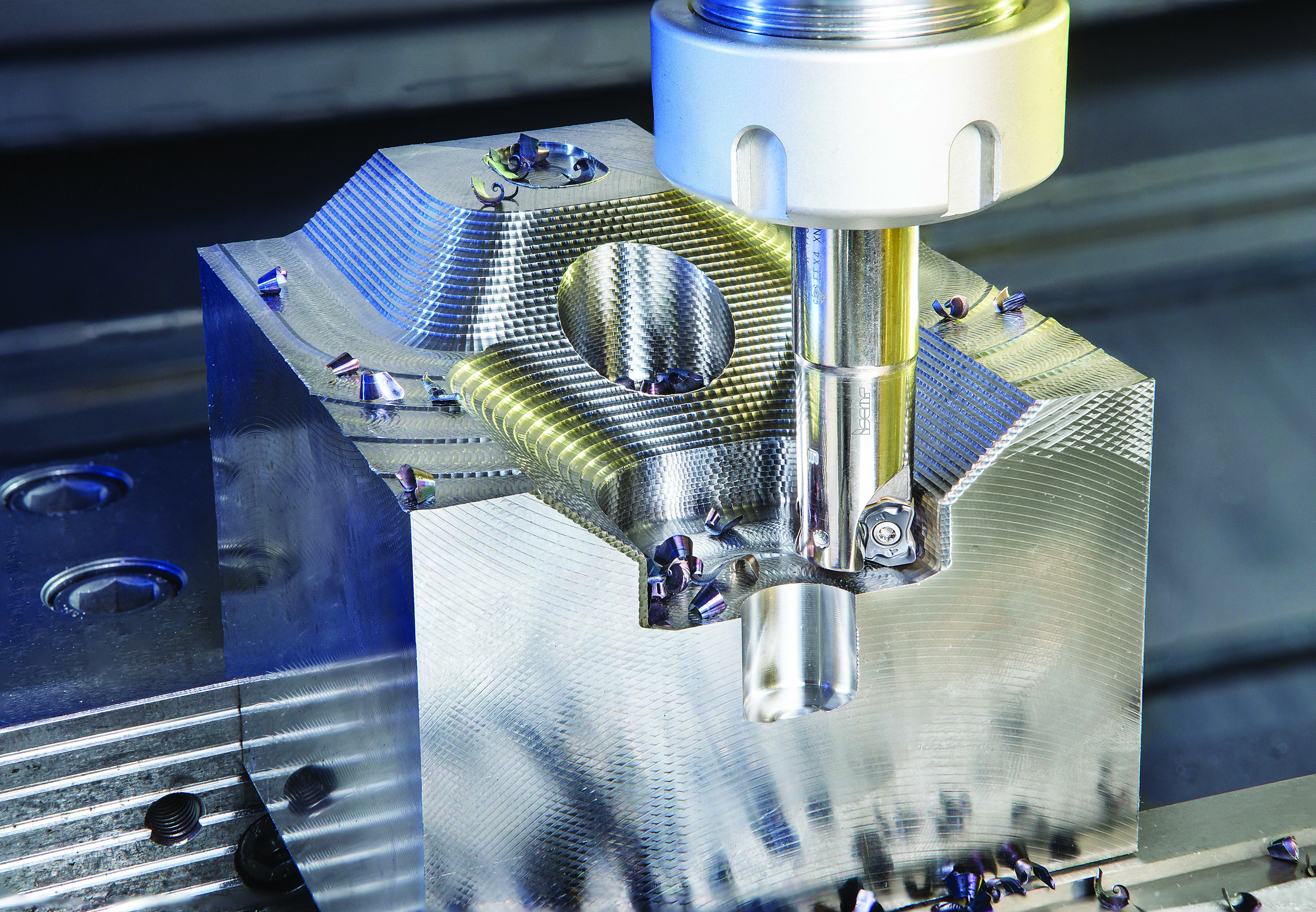
High-feed indexable insert milling tools are also widely available to up throughput. Andersson said this started several decades ago with round inserts, which have a continuously variable lead angle, depending on the DOC in relation to the radius.
“The challenge with a round insert is you basically have a small contact point,” he said.
Carlile said cutting with a round insert generally generates chips that are too thin to absorb enough heat, with the remainder going into the part and tool.
“The problem with that is it would take a giant round insert to be able to take a reasonable depth of cut,” he said.
In addition, Romlin said rough milling with a round insert limits the ability of the tool to machine a shoulder, leaving a large scallop to be removed in a subsequent operation. He said the strategy for roughing with round inserts often involved starting with a large cutter and following with maybe two smaller inserts to rough a part.
The movement away from rough milling with round inserts to high-feed milling reduced the required size and number of cutters, as well as the size of the remaining corner scallop, he said.
“It was a big improvement in process reliability, productivity and stability because the force being applied is less as you start to use the high-feed concept,” Romlin said. “This is one of our fastest-growing product areas, supporting the need for productivity improvements in the manufacturing industry. The high-feed concept is now an established machining method.”
For example, Seco Tools introduced the High Feed Square Cut size 14 milling system late last year. The toolmaker reports that the single-sided, straight-edge insert geometries of the system are suitable for high-feed ramping, pocketing, plunging, facemilling and copy
milling.
A Shallow Approach
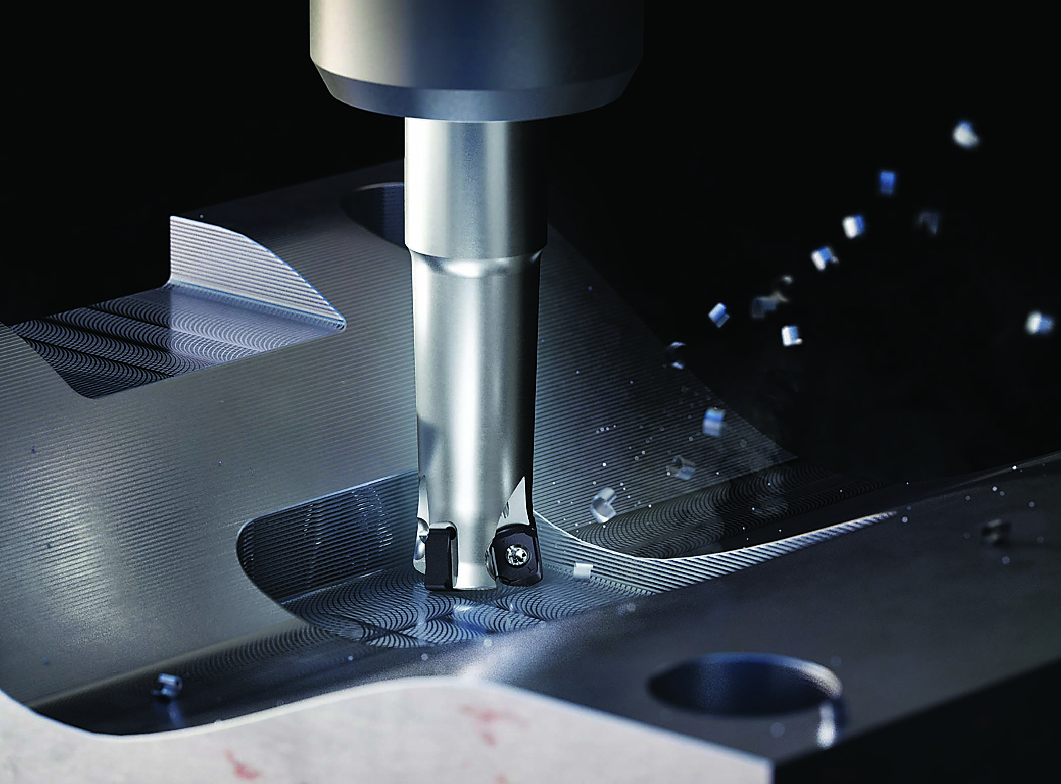
Bokram said high-feed milling tools use a simple design feature to fundamentally change machining parameters, often resulting in significantly higher total metal removal rates than conventional 45- and 90-degree designs. By reducing the approach angle of the cutter to 15 to 20 degrees, the resultant average chip thickness is reduced, which commonly is known as chip thinning.
“In order to increase the chip thickness to the ‘normal’ range for the insert edge geometry, the feed rate (ipm) must be increased,” he said. “The result is higher cutting speeds and ultimately higher metal removal rates.”
Carlile said Iscar furnishes cutters with a variety of lead angles to enable different chip thinning capabilities. The lead goes down to 9 degrees with the Mill4Feed line while a newer offering, the Logiq4Feed, has a 17-degree lead for reduced chip thinning.
He said moderate-feed milling with a 30-degree lead angle, for example, is an option when warranted.
“If the machine can’t do linear travel fast enough,” Carlile said, “just increase your lead angle and take a deeper depth of cut.”
(Editor’s note: The lead angle is the angle between the side-cutting edge of the insert and the line parallel to the axis of rotation while the approach angle is the angle between the side-cutting edge of the insert and the line perpendicular to the axis of rotation.)
However, drawbacks exist. Bokram said a high-feed mill can impart poor surface finishes, so it’s applied only for roughing, and the DOCs are restricted because of the shallow approach angle.
“In the end,” he said, “the user must calculate the comparative metal removal rates to alternative milling system designs, based on the milling operations they are performing.”
Nonetheless, Bokram said that shallow approach angle causes the net resultant machining forces to be exerted mainly along the axis of the milling cutter.
“This means that high-feed designs are useful for long-reach applications because they generate very little vibration,” he said. “They also minimize radial force stresses on the spindle.”
Bokram said a common application for high-feed mills is helical interpolation, in which the high metal removal rate provides a fast, economical way to produce a large-diameter hole or counterbore, though more slowly than an appropriately sized drill.
“That said, the milling method requires significantly less horsepower than drilling from solid,” he said, “so the milling solution is often used when the customer is restricted by low-power machines.”
Andersson said one issue for high-feed cutters results from users’ perception of the capabilities of the tools.
“The big problem people have with high-feed cutters is underfeeding them,” he said.
Andersson said YG-1 Tool’s high-feed cutter has a 10-degree lead angle, which directs almost all the cutting forces into the spindle.
“You gain a lot of stability compared to a 90-degree shoulder mill where the forces are predominantly radial, causing greater stress on the spindle and risking vibration issues,” he said.
No single indexable insert technology, however, is a magic bullet.
“You have to look at the entire process to drive down production costs,” Andersson said. “You can’t pick tooling in a vacuum. When you are talking about new technologies, it all comes down to how you build new technology into your new release or product to aid not only in having the right speed and maximum chip control, but the absolute key part is predictability.”
For more information from Iscar USA about its high-feed indexable insert milling tools, view a video presentation at cteplus.delivr.com/2swtt
Tools for the Times
As indexable inserts evolve over time, so does a toolmaker’s relationship with its customers — sometimes fairly abruptly. Jan Andersson at YG-1 Tool (USA) said there’s been a paradigm shift over the past decade or so in how tool suppliers interact with customers as the metalcutting sector has transitioned from having one manufacturing engineer per production line or work cell and all machines being run by machinists to having one manufacturing engineer overseeing the facility as machine operators replace machinists.
“Traditionally, manufacturing engineers were not only designing and setting up new components and new production lines, but they were also working on continuous improvement,” he said. “But if you have one manufacturing engineer for the plant, there is no time for continuous improvement. That time is spent being a firefighter.”
Andersson said responsibility for continuous improvement has shifted to tool manufacturers.
“The support function of the tooling manufacturer changed over the years,” he said. “It’s much more technical now.”
In addition, machine operators don’t have a journeyman machinist’s in-depth knowledge and are tasked mainly with activities, such as changing parts, pushing the start button and indexing inserts, Andersson said. In contrast, a machinist can make on-the-fly changes and tweak a process to improve it.
“An operator doesn’t necessarily have the knowledge to do so,” he said. “Sometimes they don’t have the authority to do so.”
In response, cutting tool manufacturers had to focus on developing products that deliver a high level of reliability, predictability and user-friendliness for part manufacturers, said David Romlin at Seco Tools.
“They don’t want to have any technical question marks in terms of indexing and handling the tools,” he said. “They want to do that with limited instructions. That is a challenge to provide safe solutions where you cannot make mistakes.”
Romlin said there is also a movement away from having a large inventory of tools with different variances. Instead, tool manufacturers must produce cutting tool designs and grades that are suitable for a broader window of applications than in the past.
Customers additionally are looking for new avenues to partner and integrate with tool suppliers, said Robert Bokram at Ceratizit USA.
“They are seeking ways to integrate Industry 4.0 technologies to expand the automatization of machining functions and eliminate manual intervention,” he said. “This requires the digitalization of multiple machining functions and the capacity to provide reliable technical support remotely, especially in today’s environment where plant access might be hindered by company policies surrounding employee safety.”
Automating functions like process and tool wear monitoring, tool failure and collision detection, and adaptive feed control can reduce tool costs, tool breakages, scrap and overloads, Bokram said, noting that Ceratizit offers ToolScope for doing those tasks and more.
“Self-learning functions optimize real-time operations with adaptive control limits based on actual machining and tooling conditions,” he said, “so each machine can adaptively adjust machining parameters to operate at optimal conditions.”
One shift for tool manufacturers is a result of a change not in customer relationships but the climate. As the automotive industry transitions from internal combustion engines to electric motors, Keith Carlile at Iscar said toolmakers will find more competition for cobalt, a key ingredient in both carbide cutting tools and lithium-ion batteries. He predicts that cutting tools will need to be designed to help conserve carbide while more emphasis will be placed on recycling the hard metal.
— Alan Richter
Contact Details

Contact Details
Contact Details

Contact Details

Related Glossary Terms
- approach angle
approach angle
Angle between the insert’s side-cutting edge and the line perpendicular to the milling cutter’s axis of rotation. Approach angle, which is also known as cutting edge angle, is used with metric units of measurement. See lead angle.
- chipbreaker
chipbreaker
Groove or other tool geometry that breaks chips into small fragments as they come off the workpiece. Designed to prevent chips from becoming so long that they are difficult to control, catch in turning parts and cause safety problems.
- clearance
clearance
Space provided behind a tool’s land or relief to prevent rubbing and subsequent premature deterioration of the tool. See land; relief.
- counterbore
counterbore
Tool, guided by a pilot, that expands a hole to a certain depth.
- depth of cut
depth of cut
Distance between the bottom of the cut and the uncut surface of the workpiece, measured in a direction at right angles to the machined surface of the workpiece.
- facemilling
facemilling
Form of milling that produces a flat surface generally at right angles to the rotating axis of a cutter having teeth or inserts both on its periphery and on its end face.
- feed
feed
Rate of change of position of the tool as a whole, relative to the workpiece while cutting.
- flank wear
flank wear
Reduction in clearance on the tool’s flank caused by contact with the workpiece. Ultimately causes tool failure.
- gang cutting ( milling)
gang cutting ( milling)
Machining with several cutters mounted on a single arbor, generally for simultaneous cutting.
- helix angle
helix angle
Angle that the tool’s leading edge makes with the plane of its centerline.
- indexable insert
indexable insert
Replaceable tool that clamps into a tool body, drill, mill or other cutter body designed to accommodate inserts. Most inserts are made of cemented carbide. Often they are coated with a hard material. Other insert materials are ceramic, cermet, polycrystalline cubic boron nitride and polycrystalline diamond. The insert is used until dull, then indexed, or turned, to expose a fresh cutting edge. When the entire insert is dull, it is usually discarded. Some inserts can be resharpened.
- interpolation
interpolation
Process of generating a sufficient number of positioning commands for the servomotors driving the machine tool so the path of the tool closely approximates the ideal path. See CNC, computer numerical control; NC, numerical control.
- lead angle
lead angle
Angle between the side-cutting edge and the projected side of the tool shank or holder, which leads the cutting tool into the workpiece.
- metalcutting ( material cutting)
metalcutting ( material cutting)
Any machining process used to part metal or other material or give a workpiece a new configuration. Conventionally applies to machining operations in which a cutting tool mechanically removes material in the form of chips; applies to any process in which metal or material is removed to create new shapes. See metalforming.
- milling
milling
Machining operation in which metal or other material is removed by applying power to a rotating cutter. In vertical milling, the cutting tool is mounted vertically on the spindle. In horizontal milling, the cutting tool is mounted horizontally, either directly on the spindle or on an arbor. Horizontal milling is further broken down into conventional milling, where the cutter rotates opposite the direction of feed, or “up” into the workpiece; and climb milling, where the cutter rotates in the direction of feed, or “down” into the workpiece. Milling operations include plane or surface milling, endmilling, facemilling, angle milling, form milling and profiling.
- milling cutter
milling cutter
Loosely, any milling tool. Horizontal cutters take the form of plain milling cutters, plain spiral-tooth cutters, helical cutters, side-milling cutters, staggered-tooth side-milling cutters, facemilling cutters, angular cutters, double-angle cutters, convex and concave form-milling cutters, straddle-sprocket cutters, spur-gear cutters, corner-rounding cutters and slitting saws. Vertical cutters use shank-mounted cutting tools, including endmills, T-slot cutters, Woodruff keyseat cutters and dovetail cutters; these may also be used on horizontal mills. See milling.
- milling machine ( mill)
milling machine ( mill)
Runs endmills and arbor-mounted milling cutters. Features include a head with a spindle that drives the cutters; a column, knee and table that provide motion in the three Cartesian axes; and a base that supports the components and houses the cutting-fluid pump and reservoir. The work is mounted on the table and fed into the rotating cutter or endmill to accomplish the milling steps; vertical milling machines also feed endmills into the work by means of a spindle-mounted quill. Models range from small manual machines to big bed-type and duplex mills. All take one of three basic forms: vertical, horizontal or convertible horizontal/vertical. Vertical machines may be knee-type (the table is mounted on a knee that can be elevated) or bed-type (the table is securely supported and only moves horizontally). In general, horizontal machines are bigger and more powerful, while vertical machines are lighter but more versatile and easier to set up and operate.
- outer diameter ( OD)
outer diameter ( OD)
Dimension that defines the exterior diameter of a cylindrical or round part. See ID, inner diameter.
- parallel
parallel
Strip or block of precision-ground stock used to elevate a workpiece, while keeping it parallel to the worktable, to prevent cutter/table contact.
- rake
rake
Angle of inclination between the face of the cutting tool and the workpiece. If the face of the tool lies in a plane through the axis of the workpiece, the tool is said to have a neutral, or zero, rake. If the inclination of the tool face makes the cutting edge more acute than when the rake angle is zero, the rake is positive. If the inclination of the tool face makes the cutting edge less acute or more blunt than when the rake angle is zero, the rake is negative.
- superalloys
superalloys
Tough, difficult-to-machine alloys; includes Hastelloy, Inconel and Monel. Many are nickel-base metals.
- undercut
undercut
In numerical-control applications, a cut shorter than the programmed cut resulting after a command change in direction. Also a condition in generated gear teeth when any part of the fillet curve lies inside of a line drawn tangent to the working profile at its point of juncture with the fillet. Undercut may be deliberately introduced to facilitate finishing operations, as in preshaving.
- wiper
wiper
Metal-removing edge on the face of a cutter that travels in a plane perpendicular to the axis. It is the edge that sweeps the machined surface. The flat should be as wide as the feed per revolution of the cutter. This allows any given insert to wipe the entire workpiece surface and impart a fine surface finish at a high feed rate.
Author

Alan holds a bachelor’s degree in journalism from Southern Illinois University Carbondale. Including his 20 years at CTE, Alan has more than 30 years of trade journalism experience.
Contributors
Ceratizit USA Inc.
800-783-2280
www.ceratizit.com
Iscar USA
817-258-3200
www.iscarusa.com
Seco Tools LLC
800-832-8326
www.secotools.com
YG-1 Tool (USA) Co.
800-765-8665
www.yg1usa.com
