Machines with simple user interfaces that can work directly from CAD data files are expanding the metalworking industry's application of coordinate measuring.
Many shops have been attracted to the promise of coordinate measuring. In theory, a machine that can probe specific places on part features and calculate measurements based on the coordinates of those probed points should be able to measure features more quickly and accurately than a hand-held gage. And, as an alternative to measuring with dedicated gaging fixtures, coordinate measuring with machines that can be reprogrammed should offer greater flexibility and faster changeovers when parts are altered or new parts are introduced. Shops that have been able to implement coordinate measuring have certainly enjoyed these benefits, but, despite its advantages, the practice of coordinate measuring hasn't become as widespread as expected. Until now, three roadblocks have kept the metalworking industry from taking full advantage of coordinate-measuring technology: software that is less than easy to use, software that cannot use design data for inspection, and software that works only on one type of CMM.
Recently, a new generation of software has entered the market to help CMM users overcome these obstacles. This software can use data from a part's CAD file to produce a program written in a standard CMM format. The software is easy to work with, and it can be used to control any CMM. Users who install this CAD-based software are finding that it allows them to seamlessly integrate the measuring process into their manufacturing operations.
The Ease-of-Use Issue
Measuring technology is essentially software and motion control. The probe has to be precisely guided to each point on the part, and the machine must have the necessary algorithms to translate the probe's contact points into a measurement of a part feature. CMMs have always been capable of these precise movements and measurements, but to take advantage of the machine's full capabilities, the user needed computer programming skills as well as a knowledge of metrology. It has typically been the CMM operator's responsibility to generate full inspection part programs and to modify those programs when necessary. To perform these programming tasks, the operator had to be proficient not simply in general CMM software, but in the application software controlling the specific CMM sitting on the company's inspection-room floor.
Traditionally, this software has not been easy to use. Some of these difficulties are inherent in the task of coordinate measuring. A CMM programmer must contend with alignment systems and a variety of databases to produce a usable inspection part program. In addition, the programming task has been complicated by the proprietary nature of most CMM software and the software's lack of intuitive interfaces.
Being a computer-driven machine that must execute prewritten part programs, a CMM must be programmed. But on the shop floor, programmers/operators spend less than 10% of their shifts using their expertise to program the machine. The rest of the time they are standing by the CMM monitoring the cycle. This is an inefficient use of the programmers' skills, and shops, which are finding programmers in short supply because of the skillset required, cannot afford to have such highly trained people standing idle. As an alternative to using expensive programming experts to operate the machine, shops have expected their operators to handle the programming duties. But this has raised issues about the CMM's ease of use.
The CMM industry has tried several methods to create machines that operators can program easily. One approach has been to reduce the machines' core functionality and simplify the user interface. However, the software that accomplishes this is of limited use unless the measuring task is relatively simple.
Simplified software also limits the operator's progress in the job. Most people grow into their occupations as they become familiar with the tasks involved. An expert CMM operator, for instance, can use the machine to perform much more complicated measuring routines than a novice. But if the CMM's software limits the operator to only simple tasks, neither the operator's expertise nor the machine's capabilities are put to good use. Without a very expensive upgrade for the CMM, the shop will never be able to tap the machine's full potential.
As many users have discovered, simply redesigning software for the Windowsª environment isn't the answer either. Regardless of the platform, the interface must present the user with clear choices in an easy-to-understand format if it is to be inviting for CMM operators, who typically do not have sophisticated computer skills. Up until this point, shops have had to make an unsatisfactory choice between simple software that is easy to use and powerful software that is difficult to use.
CAD-Based Inspections
A better alternative is to separate the CMM programming and operating responsibilities. This allows the person with the appropriate skills to concentrate on programming. If there is not enough CMM work to occupy all of the programmer's time, these same skills can be used to program the shop's CNCs.
For a shop to separate the programming and operation duties, it must have software that allows CMM programming to be performed on another computer and downloaded to the CMM when the program is needed. True CAD-based metrology software allows such offline programming. In addition, it allows CAD geometry to be used on the machine for comparing measurement results directly to CAD files, reverse engineering, or providing pictorial output of measured results.
This new range of software provides graphical programming, intelligent measuring, surfacing, pictorial output, and SPC, fully linking 3-D CAD data with the CMM inspection process. It is what manufacturing increasingly needs: CAD-in and CAD-out measuring so that the measured component is compared directly and automatically to original design data, saving time in programming and inspection.
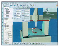
Figure 1: The actions of a Sheffield CMM, upgraded with a DMIS/CAD-based control, are simulated on-screen.
Fully CAD-integrated measuring software is now affordable and easily retrofittable to most older CMMs. Mechanically, these older machines may have many years of useful life left. In a typical retrofit, mechanical systems such as the reader heads, motors, drive systems, and limit switches are left in place. The machine is upgraded with a new wiring harness, a new 32-bit architecture controller, a new PC, and new software. The new equipment is necessary because the older systems are not designed to handle the processing speeds the software requires (Figure 1).CAD-based measuring software is in step with the growing use of CAD and computer-integrated-manufacturing (CIM) systems in even the smallest shops. CMMs that can be programmed through CAD files make it easy for shops to integrate coordinate measuring into their CIM environment. By programming CMMs using original CAD data rather than programs written and entered at the machine, shops can see up to a 25-fold increase in their measuring productivity.
User-Friendly DMIS
Figure 2: This image from the VirtualDMIS CAD-based coordinate-measuring software from International Metrology Systems Ltd. shows the simple user interface that guides nonprogrammers through a part-measuring program.The standard that allows two-way CAD-to-CMM communication is DMIS 3.0 - the ANSI dimensional measurement interface standard, which was created in the 1980s. DMIS provides a universal language for programming any CMM without using a translator. Until now, CMM builders have not taken advantage of this capability, preferring to use their own language and software products to maintain a proprietary lock on their systems' controllers. The latest CAD-based CMM control software takes a different approach. It makes use of the DMIS standard in a Windows environment, presenting its commands and routines as icons on the computer screen. With the DMIS-text-based language hidden behind a logical sequence of icons in the user interface, even nonprogrammer operators can program the machine (Figure 2).
Programmers with more advanced skills can edit the full DMIS simply by clicking on the appropriate icon and cutting and pasting sections of the program. The software also allows the programmer to edit the DMIS directly for tasks such as adding points or changing point pickup locations. The software allows the programmer to write or edit the programs offline, leaving the CMM itself to measure parts without interruption.
This DMIS/CAD-based software is typically a 32-bit Windows 95 or NT package, featuring a graphical interface, intelligent measurement, surfacing, and pictorial images. A logical solution is to group all icons on a single screen to make their software even easier to follow and use. The large graphical area, modeled after those on CAD packages, minimizes screen clutter.
CAD surface data can be imported via all CAD formats and displayed as a true solid model of the CMM parts and fixtures. The software can present operators with digitized images to help them verify the setup and program before inspection begins. The OpenGL-driven software displays a picture of the part being measured, the fixture, the CMM structure, and the probe.
With a Windows-based interface, CAD-based CMM software can build all measuring functionality into toolbars to guide user choices. One version of this type of software currently on the market features a toolbar to guide function selection and another toolbar that can be configured by the user to include all the tasks required to measure a part, such as checking a point, plane, or other part feature. With the CAD model on the monitor, the operator uses a mouse to click on a feature, and the CMM begins the programmed measurement guided by the CAD data. These measurement routines can be performed on an actual part or on a virtual part in a simulation.
Because this particular software is CAD-based, it can offer intelligent feature determination to automatically confirm the feature being measured, telling the operator whether the feature is a point, line, plane, or hole. The software can then use this information to construct the part graphically, offering the user a picture of the part being checked. A vertical toolbar includes the features to be measured, and next to it another vertical bar lists the measuring database for the workpiece.
Companies offering DMIS/CAD-based coordinate-measuring software have designed their programs to be easily mastered. Even employees who have not performed measuring duties in the past can teach themselves how to operate a CMM with this software. The software companies typically offer multimedia help in voice, video, or text formats. They also make help menus a part of the software. Some even offer a voice description of DMIS code to assist users in learning the DMIS standard and visual tutorials to coach the operators through complex inspection routines.
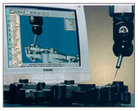
Figure 3: DMIS/CAD-based CMM control software can create simulations that allow the user to preview the part-measuring program's actions.One software package includes a virtual CMM that simulates the operation of a wide range of brands (Figure 3). By running this software, programmers can optimize their programs, simulate measuring routines, and verify their programs' ability to measure the part. The simulation graphically displays 3-D models of components and fixtures and provides automatic collision detection. It also assures CMM performance with built-in routines to check machine accuracy, including the use of ball-bar, step-gage, and Renishaw gages.
Simpler User Interfaces
Although sophisticated measuring programs can be built with DMIS/CAD-based CMM software, running these programs can be a relatively simple matter. The DMIS program that actually controls the machine remains transparent to the operator. Selecting an icon on the computer screen starts the programs, which have already been written and prequalified by a skilled CMM programmer. Users can tailor the interface to suit the measuring tasks to be performed. System, or back room, administration can select the programs for the operator to run and group together on a single screen the icons for all of the programs the operator will need. The operator's function is to simply select and run the programs, inspect the parts, and present the results to manufacturing management. With the use of a touchscreen, the operator does not even need to use a mouse or keyboard.
A CMM with a simple, intuitive interface does not require operators with sophisticated programming skills. A shop can devote its employees with those skills to programming, while employees with lesser skillsets can be assigned to operate the CMM. The training curve for an operator using DMIS/CAD-based CMM software is typically no longer than an hour. On the other hand, if programming is necessary, the programmer can access every icon via the touchscreen.
With a CMM that can be adapted to meet the needs and sophistication of the user, shops can distribute their available skillsets more efficiently. The broader use of CMM software based on standard CAD and DMIS programming routines should ease the labor shortage as well, because shops will no longer need to look for people who have experience programming a particular brand of CMM.
With new software to break through the roadblocks that have kept manufacturers from adopting coordinate-measuring technology, the metalworking industry should see the use and the value of CMMs increase. And with this growing acceptance of CMMs with standardized easy-to-use controls, manufacturers will be better able to utilize their operators, programmers, and equipment, and more effectively control their processes.
About the Author
Keith Mills is president of International Metrology Systems, Livonia, MI.
Related Glossary Terms
- 3-D
3-D
Way of displaying real-world objects in a natural way by showing depth, height and width. This system uses the X, Y and Z axes.
- computer-aided design ( CAD)
computer-aided design ( CAD)
Product-design functions performed with the help of computers and special software.
- computer-integrated manufacturing ( CIM)
computer-integrated manufacturing ( CIM)
Theoretically, an approach under which all phases of production—including management, sales, order processing, design, quality control and chipmaking—are controlled or monitored by interconnected computers. Practically, a term applied to systems approximating the ideal.
- fixture
fixture
Device, often made in-house, that holds a specific workpiece. See jig; modular fixturing.
- metalworking
metalworking
Any manufacturing process in which metal is processed or machined such that the workpiece is given a new shape. Broadly defined, the term includes processes such as design and layout, heat-treating, material handling and inspection.
- metrology
metrology
Science of measurement; the principles on which precision machining, quality control and inspection are based. See precision machining, measurement.
- solid model
solid model
3-D model created using “building blocks.” This is the most accurate way of representing real-world objects in CAD.
- statistical process control ( SPC)
statistical process control ( SPC)
Statistical techniques to measure and analyze the extent to which a process deviates from a set standard.
- tap
tap
Cylindrical tool that cuts internal threads and has flutes to remove chips and carry tapping fluid to the point of cut. Normally used on a drill press or tapping machine but also may be operated manually. See tapping.