T-slot clamps are tried-and-true accessories for milling applications — so much so that if you have a milling machine, chances are that you have a set of T-slot clamps. Besides clamping, these clamps can be used to set up work stops and fixturing, which I’ll get to in this article.
These clamps generally are used to clamp a workpiece to a machine table for machining. Standard sets include studs of various lengths with special nuts that fit into milling machine table T-slots and heavy-duty hex nuts to hold down the associated clamps. The clamps are different lengths and are used with riser blocks that have steps to allow the clamps to be positioned at assorted heights from the machine table surface. T-slot nuts are applied with studs of varying length or T-slot bolts of varying length with clamps and step blocks to set the clamp at the appropriate height for the workpiece.
Step blocks are available with thicknesses of 25.4 mm (1"), 38.1 mm (1.5") or 50.8 mm (2"). When using a clamp setup consisting of a clamp with one end resting on a standard 25.4-mm-thick step block, employing a large-diameter flat washer under the step block is convenient. The washer assures stability of the block when it straddles a T-slot. A flat washer for a 25.4 mm bolt with an outside diameter of 63.5 mm (2.5") works well with standard step blocks.
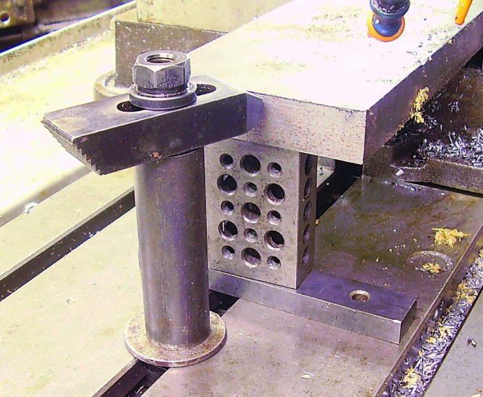
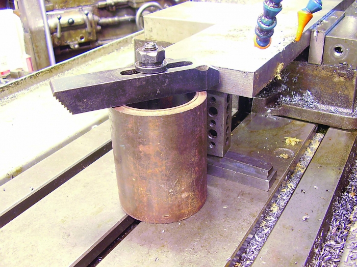
Two setups are shown using standard T-slot hardware with pieces of steel tubing used as risers. Image courtesy of B. Taylor
The T-slot clamps also can be used as work stops. For example, if a workpiece is held with a milling vise, it might be useful to have a work stop at some distance from the vise. The photographs show two such setups using standard T-slot hardware with pieces of steel tubing used as risers. The tube sets the vertical height of the clamp, and the nose of the clamp is utilized as the work stop. Simply place the workpiece where you want it, touch the nose of the clamp against the workpiece, tighten the clamp nut, and you have it.
This method can be used to make a very rigid stop. When working with heavy workpieces on a milling machine, it’s nice to use a work stop that doesn’t move or deflect from being bumped by a workpiece. Larger-diameter tubing with a longer clamp makes a more rigid stop. In the photo with the smaller-diameter tube, note the flat washer under the tube. Use 4.7625 mm (0.1875") wall or heavier tubing. The bigger setup uses an 88.9 mm (3.5") outer diameter × 9.525 mm (0.375") wall tubing with a 152.4 mm (6") long clamp. The smaller setup applies a 31.75 mm (1.25") OD × 4.7625 mm wall tubing with a 101.6 mm (4") long clamp.
Or maybe a job requires a workpiece to be clamped to a table or on risers so cutting tools can pass through, and there are a few parts to make. Two or three clamps can be set around the workpiece to make quick, easy fixturing. In that case, it’s handy to have a few pieces of 50.8-mm-long threaded rod that fit the clamping nuts so clamps can be bolted right to the table.
My shop makes components for industrial machinery, so steel tubing is used from time to time. That is a good reason to hold on to bits of tube. I hope that this column is useful out there.
Related Glossary Terms
- flat ( screw flat)
flat ( screw flat)
Flat surface machined into the shank of a cutting tool for enhanced holding of the tool.
- gang cutting ( milling)
gang cutting ( milling)
Machining with several cutters mounted on a single arbor, generally for simultaneous cutting.
- milling
milling
Machining operation in which metal or other material is removed by applying power to a rotating cutter. In vertical milling, the cutting tool is mounted vertically on the spindle. In horizontal milling, the cutting tool is mounted horizontally, either directly on the spindle or on an arbor. Horizontal milling is further broken down into conventional milling, where the cutter rotates opposite the direction of feed, or “up” into the workpiece; and climb milling, where the cutter rotates in the direction of feed, or “down” into the workpiece. Milling operations include plane or surface milling, endmilling, facemilling, angle milling, form milling and profiling.
- milling machine ( mill)
milling machine ( mill)
Runs endmills and arbor-mounted milling cutters. Features include a head with a spindle that drives the cutters; a column, knee and table that provide motion in the three Cartesian axes; and a base that supports the components and houses the cutting-fluid pump and reservoir. The work is mounted on the table and fed into the rotating cutter or endmill to accomplish the milling steps; vertical milling machines also feed endmills into the work by means of a spindle-mounted quill. Models range from small manual machines to big bed-type and duplex mills. All take one of three basic forms: vertical, horizontal or convertible horizontal/vertical. Vertical machines may be knee-type (the table is mounted on a knee that can be elevated) or bed-type (the table is securely supported and only moves horizontally). In general, horizontal machines are bigger and more powerful, while vertical machines are lighter but more versatile and easier to set up and operate.
- outer diameter ( OD)
outer diameter ( OD)
Dimension that defines the exterior diameter of a cylindrical or round part. See ID, inner diameter.
- outer diameter ( OD)2
outer diameter ( OD)
Dimension that defines the exterior diameter of a cylindrical or round part. See ID, inner diameter.
Author

Brandt Taylor is owner of Berlin, Massachusetts-based Taylor Engineering, a machine shop.
