The challenge of threading
The challenge of threading
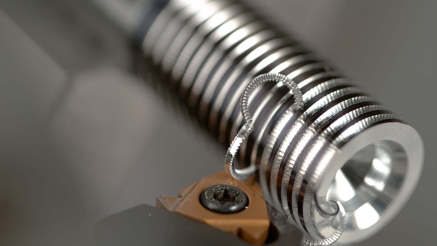
When done right, threading is very satisfying.
Threading is the most challenging of the basic machining operations. Countless combinations of thread forms and thread classes can complicate tool selection and programming.
Understanding thread requirements is the first step toward success. When properly specified, the thread callout not only contains the basic thread size like 10-24 or ¼-20 but specifies the thread class, which controls the fit between mating components, and the thread form, also known as the thread series, which designates thread geometry.
The class of fit is denoted by a 1, 2 or 3 and followed by an A or a B indicating external thread (A) or internal thread (B). For example, ¾-10 2A is ¾" major diameter with 10 threads per inch and a class 2 fit or tolerance band.
Taps, dies and other threading tools are made to produce threads to a specific thread class, so it is necessary to know which class is required to get the right tools. I learned this the hard way when I ran my family shop. We won a big order to machine aluminum extrusions, and the parts called for three holes tapped 10-24 2B. Instead of purchasing a good "go/no go" thread gauge, we checked the thread quality using a 10-24 screw and the policy of "If the screw goes in, it must be good." We proudly shipped 1,000 parts to our customer, which promptly rejected all the parts because the pitch diameter was too large. There is no way to rework a tapped hole that is too large, so we had to scrap the parts. It was an expensive lesson in proper thread fit.
Drawings clearly show geometric requirements for a workpiece, such as steps, diameters, corner radii, chamfers and other similar features. However, threading is different as drawings rarely show geometric requirements for threads. Thread geometry is governed by the thread form or thread series like UNC, UNF, BSW, BSF and NPT. The thread series dictates the size, shape, angles and various ratios that define the geometry of threads. A common designation would be ¼-20 UNC 2B, which indicates the unified thread series for coarse threads.
Once the thread series is known, a machinist or programmer can find the various ratios, dimensions and angles in a reference like Machinery's Handbook. This information is critical for determining pitch diameter, overall thread depth and radii explicit to the thread form. These details are needed to begin the thread machining or programming process.
Understanding thread requirements is the first step toward success. Cutting Tool Engineering image
In some cases, thread forms are particular to an industry. Oil and gas, for instance, conforms to specifications given by the American Petroleum Institute, which dictates thread forms designed for strength and safety in the industry. In these situations, it may be necessary to consult a specific standard to obtain accurate thread form data.
The advent of ISO standards and globalization has greatly reduced the variation in thread forms used in modern manufacturing, but older equipment can have obscure thread forms, so a machine shop can't always assume that a thread is a common form. The British Standard Whitworth thread is an
example of an early thread form used by British manufacturers that is no longer in use. However, old British machines and tools, especially those in niche industries, are still in use, and repairing them or replicating parts often requires special threading tools.
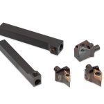
Once the thread form is known, it is necessary to select the threading tool. External and internal threads are either cut or formed. Cut threads, as the name indicates, are made by removing material from a workpiece. Formed threads are made by displacing material on a workpiece. Producing threads with a cutting tool is the most familiar method to machinists and mechanics. However, thread forming is the most productive method and is used extensively in high-volume manufacturing.
Thread cutting is the most common method for generating a thread, and almost every machinist is familiar with taps, dies and single-point threading, which was standard for many years. CNC machining utilizes these same tried-and-true threading technologies, but controls also are giving access to newer techniques.
Now we can program a lathe to cut on the point of a threading tool, the leading edge of a tool or the trailing edge of a tool. Driving the cutting edge in this manner increases tool life and improves chip control. Machining centers can be programmed to peck-tap, which mimics the manual technique in which the tap is screwed in a little and then back out some, thereby breaking the chip and allowing lubrication to advance in the hole. Difficult-to-machine materials often respond well to the addition of a peck tapping cycle.
Thread milling is probably the most significant advancement in modern thread machining. Taps, dies and similar tools used on milling machines generate a single thread size. A single-point thread mill can produce any thread size or pitch with few limitations. Thread mills also have improved thread production in difficult-to-machine materials like those used in aerospace applications.
Thread forming offers several advantages over thread cutting. The process produces a stronger thread because the grain structure of the metal is left intact. No chips are created that have to be evacuated. Thread forming tools last many times longer than cutting tools, and threading tools can run at higher speeds, making thread forming much faster.
There are some disadvantages to thread forming. It requires more power, and forces exerted on the threading tool, toolholder and workpiece are greater than the forces exerted on thread cutting tools. Hard materials and very ductile materials often can be a challenge when using thread forming tools. Thread forming becomes more difficult as material hardness increases, making broken tools more likely. Similarly, ductile materials can be difficult because they tend to be sticky and like to adhere to the threading tool, causing poor thread quality or broken tools.
Every threading job is different, which makes recommendations tough. However, I use a few general rules to make threading easier. First, I always make sure to have a well-defined requirement. If a customer does not give a full definition with size, class and form, I call and get that. Completed threads always are checked with the appropriate thread gauge, such as a plug gauge, ring gauge, thread micrometer or thread wire, and not a fastener. I needed that lesson only once.
Thread milling and single-point threading are my first choices as they are the most reliable and least finicky. If I can't thread-mill, I use a cutting tap and generally stay away from thread forming unless I think that chips will be a problem or the volume of parts is very high. Whether forming or cutting, it is important to buy good tools. Scrimp and save on drills and endmills, but don't cut corners on taps and thread mills. I have seen a $125,000 turbine wheel scrapped by a cheap tap, so don't buy inferior ones. Remember also that hand taps are for hand tapping and not appropriate for using on a machine.
General machining of external threads is best done with single-point inserts similar to grooving tools. They can cut any pitch or material with little effort. Finally, make sure that cutting fluids are maintained properly and appropriate for a material. The scrapped aluminum extrusions mentioned earlier were a result of using a coolant that was not ideal for the operation.
Threading can be a frustrating endeavor when things are going wrong. It also can be very satisfying when the right combinations of variables are used and a thread gauge slips on smoothly.