Advanced compositions and cutter designs have made ceramic inserts tough to beat for high-speed milling.
For a long time, many machinists viewed ceramic as an unsuitable milling-insert material because of its brittleness and its narrow application range. But ceramic inserts have changed. Improvements in material composition and cutter design have made today’s ceramic inserts tougher and suitable for a broader range of applications, including high-speed milling.
Ceramic has certain properties that make it a desirable alternative to carbide for high-speed milling. A major advantage of ceramic over carbide is its ability to resist heat. High-speed machining creates temperatures that can exceed 1,000° C at the cutting edge and shear interface. At these temperatures, traditional carbide inserts soften readily.
Ceramic’s resistance to high-temperature deformation and abrasive wear makes this material ideally suited for milling at high speeds. Until the recent development of tougher grades, however, ceramic inserts lacked the transverse rupture strength needed for impact resistance in interrupted cuts, thereby restricting their milling applications.
Insert Composition
Strengthening additives such as SiC and TiC have improved the abrasion resistance, strength, and fracture toughness of today’s ceramic inserts. Three types of ceramic-composite materials commonly used for milling are whiskered (Al2O3 + SiC whisker), non-whiskered (Al2O3 + TiC), and silicon nitride (Si3N4).
Whiskered ceramics are among the leading materials in the battle between toughness and hardness. The addition of alternate strengthening constituents provides maximum toughness without significantly reducing hardness. These composites are designed for the milling, turning, and grooving of high-temperature alloys and ferrous materials hardened to greater than Rc 50.
Whiskered-ceramic inserts are not recommended for machining materials softer than Rc 50, due to the toughness of the insert substrate and the chemical reaction that occurs between SiC and ferrous alloys. However, most ferrous alloys are hardened materials, making them fair game for whiskered ceramics.
While whiskered ceramics are suitable for heavy interrupted cuts, non-whiskered ceramics are used for continuous machining (i.e. non-milling) operations with minimal interruptions. Non-whiskered ceramics are designed for machining hardened ferrous alloys; silicon nitride is used for machining gray and nodular cast irons.
The transverse rupture strength of these modern ceramic composites can exceed 100,000 psi, which is more than 30% higher than earlier ceramic-composite materials. Although this doesn’t match the strength of cermet or carbide, which ranges from 250,000 to 650,000 psi, the boost in transverse rupture strength enables ceramic inserts to gain the impact resistance required in high-speed milling. In addition to these interrupted machining applications, which previously were dominated by metals and metal-matrix composites, ceramic-composite grades can now be used to remove scale without the risk of catastrophic failure. Because scale is generally harder and more abrasive than the homogeneous base material, this discontinuous machining process is particularly challenging.
Although strengthening additives have expanded their application range, ceramic inserts are far better suited for hardened rather than soft workpiece materials. During hardened-part machining, chips are much shorter and more abrasive than those formed during the machining of softer materials. The non-continuous ferrous chip does not remain in continuous contact with the hardened material, decreasing the chemical reactivity time between the tool and workpiece.
The rigorous demands of high-speed milling, including high-speed spindle capabilities and corresponding safety requirements to contain the cutter while engaged in the cut, have also led to the development of specialty cutter designs. These high-speed milling cutters are specifically designed to utilize the properties of ceramic-composite materials, particularly their high hardness and high-temperature mechanical stability.
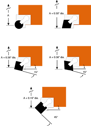
 Figure 1: Cartridge designs with pockets for various ceramic-insert geometries. Dimension A is the maximum effective cutter diameter. |
Cutter Design
High-speed milling cutters and toolholders take advantage of the compressive strength of the ceramic insert by redirecting the forces of the cut into the strongest part of the insert body. This generates additional heat in the shear zone by increasing the amount of work necessary to cause slip along shear planes. This, in turn, helps soften the material being removed at the tool-and-workpiece interface and decreases the force necessary to cause shear-plane slippage.
High-speed milling cutters typically range from 1 1/2" to 12" in diameter. The combination of a right-hand cartridge and a round insert is the standard on which all recommended machining parameters are based, because the round insert offers the strongest mechanical geometry.
Figure 1 displays typical replaceable cartridge designs for a right-hand milling cutter. The maximum effective cutter diameter (dimension A) changes to accommodate optimal presentation of each insert geometry. These additions to cutter diameter are indicated in the illustrations. Endmills are used in applications requiring cutter diameters of 3" or smaller. Endmills can be designed to use both negative-rake and positive-rake insert geometries. Negative-rake inserts offer more usable cutting edges and a stronger geometry. Their standard application is for roughing, while positive-rake inserts are typically used for finishing.
Another advantage of positive-rake inserts is reduced tool pressure. A positive-rake design allows for up to 11° in insert-geometry clearance. A ceramic insert is rarely presented at a rake angle greater than 11°, because the fragile edge doesn’t have the strength to withstand high-shear cutting conditions. The high-shear action would reduce the heat at the cutting interface and, therefore, wouldn’t provide the lower shear stress for chip slippage.
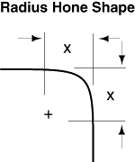
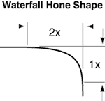
Edge preparations for ceramic milling inserts are similar to those for ceramic rough-turning inserts. The edge preparations shown in Figure 2 are more pronounced than those recommended for milling with carbide, because carbide inserts generally have higher strength and toughness than ceramic inserts.
Edge preparation B in Figure 2 is used for most general-purpose milling operations with ceramics. This edge preparation and hone allow for sufficient redirection of cutting forces to provide maximum edge strength and resistance to fracture, which are necessary for interrupted-cutting operations such as milling. Edge preparations A and C represent the least severe to the most severe standard requirement.
Edge preparations should be determined on a case-by-case basis. When selecting an edge preparation, a good rule of thumb is to start in the middle with edge preparation B and modify it, as needed, to achieve the freest cutting conditions, the required surface finish, and a normal edge-wear pattern (free of edge chipping).
Even with the proper edge preparation, rake, and cutter design, ceramic inserts won’t boost productivity if they aren’t run at optimal speeds. Adjustments must be made to standard machining recommendations when using ceramic inserts for high-speed milling.
 Figure 2: Standard edge preparations with 0.0005"/0.0010" hones for milling with ceramic inserts. |
 Figure 3: Surface-speed recommendations for turning with ceramic inserts. |
Machining Recommendations
Figure 3 shows the recommended surface speeds for single-point turning with ceramic inserts. Table 1 lists adjustments to optimize the recommended sfm for milling. Achieving the necessary sfm on small ceramic cutters may be limited by the safe operating conditions and spindle speeds of most machines that are currently available. For relatively small widths of cut, the best recommendation is to run as fast as the machine safely allows.
Table 1 shows that as the width of cut decreases, the sfm increases proportionately. The sfm recommended in Figure 3 should only be used when 100% of the width of the cutter is engaged. Remember that if a milling cutter is engaged in the full width of cut, the inserts are only cutting metal half the time. The sfm must be increased by the assigned percentage to generate and maintain sufficient heat in the shear zone of the workpiece material to reduce the force necessary to cause slip along material shear planes.
To produce good surface finishes, feed rate per revolution (feed per tooth 5 number of teeth) should be less than 1/3 of the nose radius of the insert or 1/3 of the wiper flat. This should be considered a rule of thumb for milling in general, including milling with carbide or cermet inserts. At the high velocities required for milling with ceramic inserts, feed rates should not exceed 0.004" per tooth. The recommended chipload for ceramics is approximately 1/2 the chipload for carbide.
Table 1: Adjustments to sfm for milling with ceramic inserts. |
About the Author Joseph Halloran is an applications engineer at Greenleaf Corp., Saegertown, PA.
Related Glossary Terms
- abrasive
abrasive
Substance used for grinding, honing, lapping, superfinishing and polishing. Examples include garnet, emery, corundum, silicon carbide, cubic boron nitride and diamond in various grit sizes.
- alloys
alloys
Substances having metallic properties and being composed of two or more chemical elements of which at least one is a metal.
- cast irons
cast irons
Cast ferrous alloys containing carbon in excess of solubility in austenite that exists in the alloy at the eutectic temperature. Cast irons include gray cast iron, white cast iron, malleable cast iron and ductile, or nodular, cast iron. The word “cast” is often left out.
- ceramics
ceramics
Cutting tool materials based on aluminum oxide and silicon nitride. Ceramic tools can withstand higher cutting speeds than cemented carbide tools when machining hardened steels, cast irons and high-temperature alloys.
- clearance
clearance
Space provided behind a tool’s land or relief to prevent rubbing and subsequent premature deterioration of the tool. See land; relief.
- composites
composites
Materials composed of different elements, with one element normally embedded in another, held together by a compatible binder.
- edge preparation
edge preparation
Conditioning of the cutting edge, such as a honing or chamfering, to make it stronger and less susceptible to chipping. A chamfer is a bevel on the tool’s cutting edge; the angle is measured from the cutting face downward and generally varies from 25° to 45°. Honing is the process of rounding or blunting the cutting edge with abrasives, either manually or mechanically.
- feed
feed
Rate of change of position of the tool as a whole, relative to the workpiece while cutting.
- flat ( screw flat)
flat ( screw flat)
Flat surface machined into the shank of a cutting tool for enhanced holding of the tool.
- fracture toughness
fracture toughness
Critical value (KIC) of stress intensity. A material property.
- gang cutting ( milling)
gang cutting ( milling)
Machining with several cutters mounted on a single arbor, generally for simultaneous cutting.
- grooving
grooving
Machining grooves and shallow channels. Example: grooving ball-bearing raceways. Typically performed by tools that are capable of light cuts at high feed rates. Imparts high-quality finish.
- hardness
hardness
Hardness is a measure of the resistance of a material to surface indentation or abrasion. There is no absolute scale for hardness. In order to express hardness quantitatively, each type of test has its own scale, which defines hardness. Indentation hardness obtained through static methods is measured by Brinell, Rockwell, Vickers and Knoop tests. Hardness without indentation is measured by a dynamic method, known as the Scleroscope test.
- milling
milling
Machining operation in which metal or other material is removed by applying power to a rotating cutter. In vertical milling, the cutting tool is mounted vertically on the spindle. In horizontal milling, the cutting tool is mounted horizontally, either directly on the spindle or on an arbor. Horizontal milling is further broken down into conventional milling, where the cutter rotates opposite the direction of feed, or “up” into the workpiece; and climb milling, where the cutter rotates in the direction of feed, or “down” into the workpiece. Milling operations include plane or surface milling, endmilling, facemilling, angle milling, form milling and profiling.
- milling cutter
milling cutter
Loosely, any milling tool. Horizontal cutters take the form of plain milling cutters, plain spiral-tooth cutters, helical cutters, side-milling cutters, staggered-tooth side-milling cutters, facemilling cutters, angular cutters, double-angle cutters, convex and concave form-milling cutters, straddle-sprocket cutters, spur-gear cutters, corner-rounding cutters and slitting saws. Vertical cutters use shank-mounted cutting tools, including endmills, T-slot cutters, Woodruff keyseat cutters and dovetail cutters; these may also be used on horizontal mills. See milling.
- rake
rake
Angle of inclination between the face of the cutting tool and the workpiece. If the face of the tool lies in a plane through the axis of the workpiece, the tool is said to have a neutral, or zero, rake. If the inclination of the tool face makes the cutting edge more acute than when the rake angle is zero, the rake is positive. If the inclination of the tool face makes the cutting edge less acute or more blunt than when the rake angle is zero, the rake is negative.
- titanium carbide ( TiC)
titanium carbide ( TiC)
Extremely hard material added to tungsten carbide to reduce cratering and built-up edge. Also used as a tool coating. See coated tools.
- turning
turning
Workpiece is held in a chuck, mounted on a face plate or secured between centers and rotated while a cutting tool, normally a single-point tool, is fed into it along its periphery or across its end or face. Takes the form of straight turning (cutting along the periphery of the workpiece); taper turning (creating a taper); step turning (turning different-size diameters on the same work); chamfering (beveling an edge or shoulder); facing (cutting on an end); turning threads (usually external but can be internal); roughing (high-volume metal removal); and finishing (final light cuts). Performed on lathes, turning centers, chucking machines, automatic screw machines and similar machines.
- width of cut
width of cut
Width of the milled surface, reflecting a face milling cutter’s radial engagement, and a peripheral milling cutter’s axial engagement, in the cut.
- wiper
wiper
Metal-removing edge on the face of a cutter that travels in a plane perpendicular to the axis. It is the edge that sweeps the machined surface. The flat should be as wide as the feed per revolution of the cutter. This allows any given insert to wipe the entire workpiece surface and impart a fine surface finish at a high feed rate.
