Coating technicians carefully prepare tools and parts for the PVD coating process.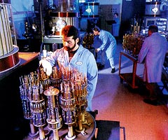
Coatings can greatly enhance carbide tool life and performance, but only if they stay in place.
The film of metal nitride or metal carbide that enhances the wear resistance and lubricity of a carbide tool is typically only 1µm to 5µm thick. This thin film must adhere to the substrate even while the forces that are generated by the cutting operation try to rip it away. The coating’s ability to withstand these forces depends in large part on the substrate’s capacity to accept and maintain a strong bond with the film. This capacity might be called the substrate’s coatability.
A number of factors can influence the coatability of a carbide tool, including the tool’s ability to withstand the coating process. Here, the PVD coating has an advantage over CVD coating, the other widely used process. CVD coating equipment operates at about 1,800°F, which is more than 60% of the carbide’s original sintering temperature. This heat can create a brittle and undesirable eta phase on the carbide’s surface that promotes edge chipping. Often, tool edges must be honed before coating to minimize the eta phase’s affects, because brittle surfaces on a sharp edge would be that much more prone to chipping. Beneficial compressive stress that may have existed in the ground, uncoated carbide surfaces also may be relieved at the relatively high CVD process temperatures, further aggravating the edge-chipping problem.
Despite these limitations, CVD coatings are still used extensively on carbide tools. The process is preferred for certain tool geometries, because it can coat inside diameters and blind holes, which are surfaces of the tool that the PVD process can’t easily reach. PVD coating is a line-of-sight process, which means that it primarily coats only surfaces that face the plasma, or source of the coating material.
For coating tools with simpler geometries, toolmakers and users can avoid some of CVD’s drawbacks by using a PVD coating. The PVD process, which typically operates in the range of 500°F to 950°F, is much friendlier to the carbide substrate. At these lower temperatures, eta phase will not form, and edge honing is not necessary. The process does not relieve the beneficial compressive grinding stress that remains in the tool as a result of manufacturing processes. In fact, some PVD processes generate additional compressive stress in the coating as the film grows, further protecting the edge from chipping.
Surface Quality
However, even the quality of a PVD coating can’t be ensured unless the surface to be coated lends proper support. Just as one would not paint over oxidized, dirty, or corroded surfaces, one should not coat over tool surfaces that are contaminated or unstable. Ideally, the structure of the surface should be the same, and in the same condition, as the bulk of the material.
This is not always the case with tools fresh from the manufacturer. To make carbide tools, manufacturers blend together hard metal carbide grains and soft cobalt metal powder. This mixture is then sintered at 2,500°F to 2,900°F to develop full structural integrity and strength. Sintering furnace atmospheres may leave a thin oxide layer on an as-sintered surface. On a coated tool this layer becomes trapped between the substrate and the coating, where it can breakdown and loosen the coating’s hold on the tool material.
Sometimes, a layer up to 15µm thick of excess cobalt will cover a sintered tool’s surface. This mottled, cobalt-rich skin is known as cobalt capping. Capping does not affect the tool life of an uncoated tool; the excess cobalt quickly wears down until the hard carbide skeleton is exposed and tool wear is stabilized. But when a capped surface is coated, the soft capping may deform and yield, causing the coating to stretch or crack or otherwise breakdown prematurely. To avoid these problems the excess cobalt must be removed by grinding or polishing before the tool is coated. A toolmaker that is planning to remove this excess cobalt might manufacture the tool slightly oversize to compensate for the material that will be lost when the capping is ground away.
Contaminants introduced during other tool manufacturing processes also can hinder the development of a strong bond. In the tool’s as-sintered state, its cobalt is soft enough to allow contaminants to become embedded easily. Grinding dust and grinding-wheel breakdown products normally carried away by coolant can cling tenaciously to the tool’s surface if the coolant is allowed to dry on the tool. Drying coolant or water can leave other residues as well. Such residues have been found to contain calcium, chlorine, silicon, magnesium, oxygen, carbon, and lime compounds. These become chemically bonded with the tool’s surface. Honing operations used to radius edges can leave aluminum oxides or silicon carbides caked on edges or as general surface contaminants.
Ridding the tool of these foreign substances can be difficult. In some PVD processes, tool surfaces receive an ion etching in the coating vessel just before the coating is applied. This removes very light films, spurious dust pArticles, and very thin oxide layers, but it cannot clean dried-on, caked-on, or embedded contaminants or rectify other gross problems with tool surfaces. Often the only way to successfully remove such dried-on contaminants from a tool is by mechanically wiping, scrubbing, or even vapor blasting the tool.
It also may be necessary to demagnetize a carbide tool that is to be coated. When the ferromagnetic cobalt in the carbide tool becomes magnetized, the tool will attract iron filings or grinding dust from the manufacturing environment. The same will happen if the filings themselves are magnetic. Unless filings are removed, they will disrupt PVD film deposition and growth.
Another source of contamination is cadmium in the braze alloys used on some carbide-tipped tools. The heat and vacuum of the coating process will cause silver brazing alloys or silver solders to lose cadmium by sublimation. This cadmium will then combine with the coating and contaminate it. When a cadmium compound is deposited on the tool, it will inhibit the performance of the coating that is deposited with it. For this reason, the silver solders used on carbide tools that are to be PVD coated should be cadmium free.
Cobalt Leaching
Cobalt leaching also might render a tool surface unsuitable for coating. Leaching is very superficial, on the order of a few microns in depth, but its affect on the carbide’s coatability can be dramatic. The problem is somewhat like washing the tar out of an asphalt roadway’s surface with a solvent. The tar is the binder that holds the roadway’s stones in place. If enough tar is washed out, the stones at the surface of the asphalt become loose. The cobalt that holds the carbide grains together in a cutting tool is like the tar in roadway asphalt. If it is leached away, the frail skeleton of carbides that remains on the surface may lack the strength and integrity to stay together or hold a coating.
A carbide tool’s cobalt binder is easily attacked and dissolved by aggressive acidic liquids such as contaminated coolant. The higher the fluid’s acidity or the longer the tool’s exposure to acidic liquids, the worse the leaching will be. Heat is another factor. The rate of cobalt leaching, following the general rule for most corrosive environments, roughly doubles with each 18° F increase in temperature. And leaching damage can be cumulative with multiple exposures to corrosive liquids.
Because longer and more frequent exposures to corrosive liquids make leaching worse, leaching often affects surfaces machined early in the tool manufacturing process more than surfaces machined later. This may happen, for example, when coolants are allowed to dwell on tool surfaces in between the numerous steps used to produce a carbide endmill. As the first surfaces to be ground, the flute surfaces will be exposed to coolants many more times than the last surfaces ground on the end teeth. An aggressive coolant will leach much more cobalt out of the flutes than it will out of the end teeth, as a result. A TiN coating over such a tool will bond poorly in the flutes, but coat the end teeth well. The presence of variable leaching damage on the same tool is a clear indication that leaching is occurring somewhere in the manufacturing process. A toolmaker that is experiencing such a problem might ask his coolant manufacturer what would reduce his coolant’s acidity. He might also dry the tool between operations to reduce its exposure to corrosive fluids.
Chlorinated fluorocarbon cleaning processes (using freon for example) have been known to lead to leaching and cobalt salt formation when excessive heat causes the chlorine ions from the CFC to dissociate and attack the cobalt binder. Even fingerprints, where body sweat contains chlorides, have been known to leave their mark on polished carbide surfaces. Currents produced in EDM operations further influence leaching.
As with cobalt capping, leaching does not seriously affect the life of an uncoated carbide tool. The loose surface grains may break away when the tool is first used, but tool wear immediately stabilizes after the frail skeleton of unsupported carbides has worn off. However, leaching as superficial in depth as half the diameter of the carbide grains can affect the integrity of the carbide tool’s surface. The loose carbide grains break away from the surface, taking any adhered coating with them. This leaves an uncoated surface exposed to premature wear. In some cases, these unsupported grains will be broken off by the compressive stress many PVD coatings impart. When this happens, tools emerge from the coating process with surface areas that appear to be uncoated.
Toolmakers can avoid much of this leaching damage by taking proper precautions during the manufacturing process. Coolants and fluids can be tested for the presence of dissolved cobalt (which can alert the manufacturer to possible leaching damage) by using cobalt-ion detection strips. More sophisticated chemical methods also are available. Leaching during tool cleaning will be minimized if a process that is nonaggressive towards cobalt metal is used. These processes include aqueous cleaning, with ultrasonics, in neutral or slightly basic baths, followed by thorough drying. It is hard to avoid surface leaching with EDMing, but this damage can be minimized by using carbon electrodes and hydrocarbon-base fluids. EDMing also can result in recast structures and cracked surfaces on carbides. Material affected in this way should be polished or ground off of critical surfaces before coating.
Detecting Problems
Figure 1: In this photograph of a Calo-tested tool, the contrast between the coating, the unleached tool surface, and the leached surface can be seen. A is the portion of the coated surface that has no grind lines. B is the Calo wear scar. C is the halo of surface-cobalt depletion where leaching has occurred. D is the uncoated matte surface about the wear scar (magnification: 355).
Figure 2: As this micrograph reveals, this tool is losing cobalt binder from its coated surface. Light-colored grains can be seen attached to the underside of the film (magnification: 65005).
Many coating services have methods and techniques that allow them to screen and assess potential problems with surfaces before coatings are applied. Often, loose surface material can be detected with a simple adhesive tape test—a problem is indicated if material adheres to the tape after it is pulled off the tool. The composition of the loose material can be determined through X-ray fluorescence (XRF) spectral analysis. This will help the coating service determine the presence of tungsten-carbide grains or other metallic contaminants. Combined with other testing techniques, XRF also can determine the percentage of cobalt in the carbide. With this data the service can quantify leaching losses. Calo testing exposes the tool’s bulk substrate material, allowing the examiner to compare the cobalt content in the interior of the tool to that of the surface. Calo testing is a variation of radial sectioning. The test generates a shallow 1mm-dia. dimple in the surface of a tool.
A visual examination of the tool can help the coating service diagnose the causes of problems that occur after coating. The ground surface of a tool that has suffered severe cobalt leaching may exhibit a patchy loss of coating. This will be oriented with the grind lines, because surface wetting for a coolant is easier in this direction. Leaching also may be indicated by the presence of loose carbide grains on the underside of the coating that has flaked off of the tool. Where carbide grains have fallen out, a new matte-finish surface will appear (Figure 1). Calo and XRF testing can be performed on a tool to confirm the presence of leaching.
At times, however, coating problems may not be obvious. With a marginal leaching or surface contamination problem, the coating coverage may look good. These flaws may be revealed with a Rockwell A-scale indentation test. When the indentation of the surface displaces substrate material, it may loosen the coating surrounding the indented area if a problem exists. If the area that is exposed by this coating loss is grainy and has a matte finish, this will indicate that the carbide grains on the tool’s surface are loose (Figure 2). If the tool’s original surface lies beneath the lost coating, this may indicate that surface contamination is the cause of the coating’s poor adhesion. If an examination of the underside of the coating flakes does not reveal the nature of the lost material, a more sophisticated assessment under a scanning electron microscope coupled with energy-dispersive spectrum analysis may be needed.
When coating problems occur, it may be helpful to know their cause. But it is more productive to detect and correct problems before the coating is applied. Customers who know what can jeopardize the success of a tool coating can address these problems before they send their tools out for coating.
About the Author
Stanley Biernat Jr. is chief metallurgist for Balzers Tool Coating, North Tonawanda, NY.
Related Glossary Terms
- alloys
alloys
Substances having metallic properties and being composed of two or more chemical elements of which at least one is a metal.
- chemical vapor deposition ( CVD)
chemical vapor deposition ( CVD)
High-temperature (1,000° C or higher), atmosphere-controlled process in which a chemical reaction is induced for the purpose of depositing a coating 2µm to 12µm thick on a tool’s surface. See coated tools; PVD, physical vapor deposition.
- coolant
coolant
Fluid that reduces temperature buildup at the tool/workpiece interface during machining. Normally takes the form of a liquid such as soluble or chemical mixtures (semisynthetic, synthetic) but can be pressurized air or other gas. Because of water’s ability to absorb great quantities of heat, it is widely used as a coolant and vehicle for various cutting compounds, with the water-to-compound ratio varying with the machining task. See cutting fluid; semisynthetic cutting fluid; soluble-oil cutting fluid; synthetic cutting fluid.
- electrical-discharge machining ( EDM)
electrical-discharge machining ( EDM)
Process that vaporizes conductive materials by controlled application of pulsed electrical current that flows between a workpiece and electrode (tool) in a dielectric fluid. Permits machining shapes to tight accuracies without the internal stresses conventional machining often generates. Useful in diemaking.
- endmill
endmill
Milling cutter held by its shank that cuts on its periphery and, if so configured, on its free end. Takes a variety of shapes (single- and double-end, roughing, ballnose and cup-end) and sizes (stub, medium, long and extra-long). Also comes with differing numbers of flutes.
- flutes
flutes
Grooves and spaces in the body of a tool that permit chip removal from, and cutting-fluid application to, the point of cut.
- grinding
grinding
Machining operation in which material is removed from the workpiece by a powered abrasive wheel, stone, belt, paste, sheet, compound, slurry, etc. Takes various forms: surface grinding (creates flat and/or squared surfaces); cylindrical grinding (for external cylindrical and tapered shapes, fillets, undercuts, etc.); centerless grinding; chamfering; thread and form grinding; tool and cutter grinding; offhand grinding; lapping and polishing (grinding with extremely fine grits to create ultrasmooth surfaces); honing; and disc grinding.
- lapping compound( powder)
lapping compound( powder)
Light, abrasive material used for finishing a surface.
- lubricity
lubricity
Measure of the relative efficiency with which a cutting fluid or lubricant reduces friction between surfaces.
- physical vapor deposition ( PVD)
physical vapor deposition ( PVD)
Tool-coating process performed at low temperature (500° C), compared to chemical vapor deposition (1,000° C). Employs electric field to generate necessary heat for depositing coating on a tool’s surface. See CVD, chemical vapor deposition.
- polishing
polishing
Abrasive process that improves surface finish and blends contours. Abrasive particles attached to a flexible backing abrade the workpiece.
- sintering
sintering
Bonding of adjacent surfaces in a mass of particles by molecular or atomic attraction on heating at high temperatures below the melting temperature of any constituent in the material. Sintering strengthens and increases the density of a powder mass and recrystallizes powder metals.
- titanium nitride ( TiN)
titanium nitride ( TiN)
Added to titanium-carbide tooling to permit machining of hard metals at high speeds. Also used as a tool coating. See coated tools.
- wear resistance
wear resistance
Ability of the tool to withstand stresses that cause it to wear during cutting; an attribute linked to alloy composition, base material, thermal conditions, type of tooling and operation and other variables.