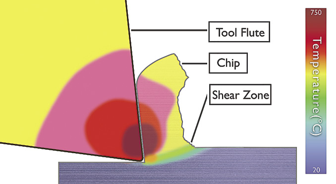
Contrary to popular belief, the cutting edges of cutting tools don’t actually produce chips. What happens is that the pressure of a rapidly spinning tool on a workpiece plasticizes part of the parent material, creating a shearing effect that forces the material to ride up the tool. The flute and tool geometries form the chip and force it away from the tool body until it breaks off and evacuates.
(Click here to view a video produced by Iscar Metals Inc. that depicts this process.)
Is there something you can take away from this improved understanding to make your CNC machining processes more effective? Indeed, there is.

Constant chip thickness is needed for keeping an optimal amount of heat in the chip and directing it from the tool and workpiece. Image courtesy CNC Software.
One of the biggest takeaways is a heightened appreciation for the roles that machining parameters and heat play when cutting metal. Heat is not always the enemy. Rather, it is an essential ingredient of the cutting process and should be carefully managed to create optimal material-removal conditions.
Advanced cutting tools can take the heat. Toolmakers protect their products with coatings that permeate and encapsulate the tool’s molecules to make them slippery and able to resist degradation due to pressure, friction and high heat levels. This protection is needed because temperatures ranging from 1,000° F to more than 3,000° F (538° C to 1,649° C) are frequently necessary to plasticize the material and achieve the desired metal-removal rate.
Therefore, it is generally a mistake to back off on the feeds and speeds to “protect” cutting tools and parts from heat damage. Heat, and lots of it, is needed within the shear zone for efficient material removal. However, that heat should not be allowed to linger, lest it migrate into the part or the cutting tool. Instead, the heat must be removed via chip formation and evacuation.
While all this may sound complicated, researchers have repeatedly demonstrated that there is a simple way to always keep cutting tools working at maximum machining efficiency (MME). Carbide cutting tools will perform better and last longer, even when machining some of the most unforgiving materials, as long as chip thickness is consistently maintained. Chip thickness—the amount of material removed by a tool during a single rotation—is based on the toolmaker’s recommendation for a specific cutting tool and workpiece material. Combinations of feeds, speeds and step-overs may be varied as long as the recommended chip thickness is maintained.
Backing off on feeds and speeds “to be safe” often results in excessive or insufficient heat, lack of shear, workhardening, or burnishing of the part, cutting tool, or both part and tool. For example, when step-overs are reduced below 25 percent, the chip will noticeably thin, often times falling below the recommended chip thickness. Feeds and speeds may need to be increased to generate chips with the appropriate thickness so that the necessary shearing condition, chip formation and heat transfer can occur. The ironic result of this is that tool life will be extended and the MRR improved at the same time.
This is where CAM software comes in. If the optimal target chip thickness for a cutting tool and workpiece has been determined to be 0.003" (0.076mm), it must be continually kept within a range of about 0.0032" and 0.0028" (0.081mm to 0.071mm) to maintain MME. This is not difficult to do, as long as the tool is removing material along a straight line. However, for most parts, toolpaths are continually interrupted by curves, corners, and tools exiting and entering the part. These are the times when MME goes out the window, unless the CAM software adapts the toolpath motion and trajectory relative to the material so that the same-size chip is cut everywhere on the part.
Some CAM packages do this by continually adjusting the cutting tool motion to keep the chip thickness consistently within a narrowly specified range. The software algorithms that achieve this are getting better as CAM developers and toolmakers partner with each other to optimize tool design and motion.
The CNC equipment found in most shops, even machines without high-speed spindles, can benefit from this approach. The CAM software you are already using may support these material-removal strategies. In this case, the only thing you have to do is invest a small amount of time to learn how to apply them.
Part 2 of this column, which will appear in the December issue, will examine the impact MME has on a manufacturing business.
Related Glossary Terms
- backing
backing
1. Flexible portion of a bandsaw blade. 2. Support material behind the cutting edge of a tool. 3. Base material for coated abrasives.
- burnishing
burnishing
Finishing method by means of compressing or cold-working the workpiece surface with carbide rollers called burnishing rolls or burnishers.
- computer numerical control ( CNC)
computer numerical control ( CNC)
Microprocessor-based controller dedicated to a machine tool that permits the creation or modification of parts. Programmed numerical control activates the machine’s servos and spindle drives and controls the various machining operations. See DNC, direct numerical control; NC, numerical control.
- computer-aided manufacturing ( CAM)
computer-aided manufacturing ( CAM)
Use of computers to control machining and manufacturing processes.
- metal-removal rate
metal-removal rate
Rate at which metal is removed from an unfinished part, measured in cubic inches or cubic centimeters per minute.
- toolpath( cutter path)
toolpath( cutter path)
2-D or 3-D path generated by program code or a CAM system and followed by tool when machining a part.
- workhardening
workhardening
Tendency of all metals to become harder when they are machined or subjected to other stresses and strains. This trait is particularly pronounced in soft, low-carbon steel or alloys containing nickel and manganese—nonmagnetic stainless steel, high-manganese steel and the superalloys Inconel and Monel.
Author

Stas Mylek is applications adviser for CNC Software Inc., Tolland, Conn. For more information about the company’s Mastercam CAD/CAM software, call (800) 228-2877 or visit www.mastercam.com.
