Big parts, big questions

Author Christopher Tate
Published
August 13, 2020 - 10:00am

Power generation components are enormous compared with the automotive and aerospace parts that I worked with before coming to Mitsubishi Hitachi Power Systems Americas Inc. The machines shown to me during my interview there were much larger than anything I had used. I had seen photographs on the internet of big machines, but photos mask the true scale of the components and the machines used to make them.

It is easy to be intimidated by the size of power generation manufacturing. Several questions entered my mind as I realized what I faced: How do I hold these parts? Do they act differently from small parts? How do I estimate cycle times? What cutting tools do I use? The answers that came surprised me.

Ask and Receive

Most of our turning is done on vertical turret lathes. Unlike smaller turning centers, large machines typically do not have self-centering chucks. Most of the time, we use chuck jaws mounted to a machine table, which creates the same type of setup as a four-jaw chuck on a small toolroom lathe. Each jaw moves independently, allowing a machinist to accurately align a part before machining. Part geometry occasionally does not lend itself to jaw use, in which case we clamp the part in place with threaded studs and strap clamps, much like using a faceplate on a manual lathe. (Only old-timers remember using a faceplate with clamps.)


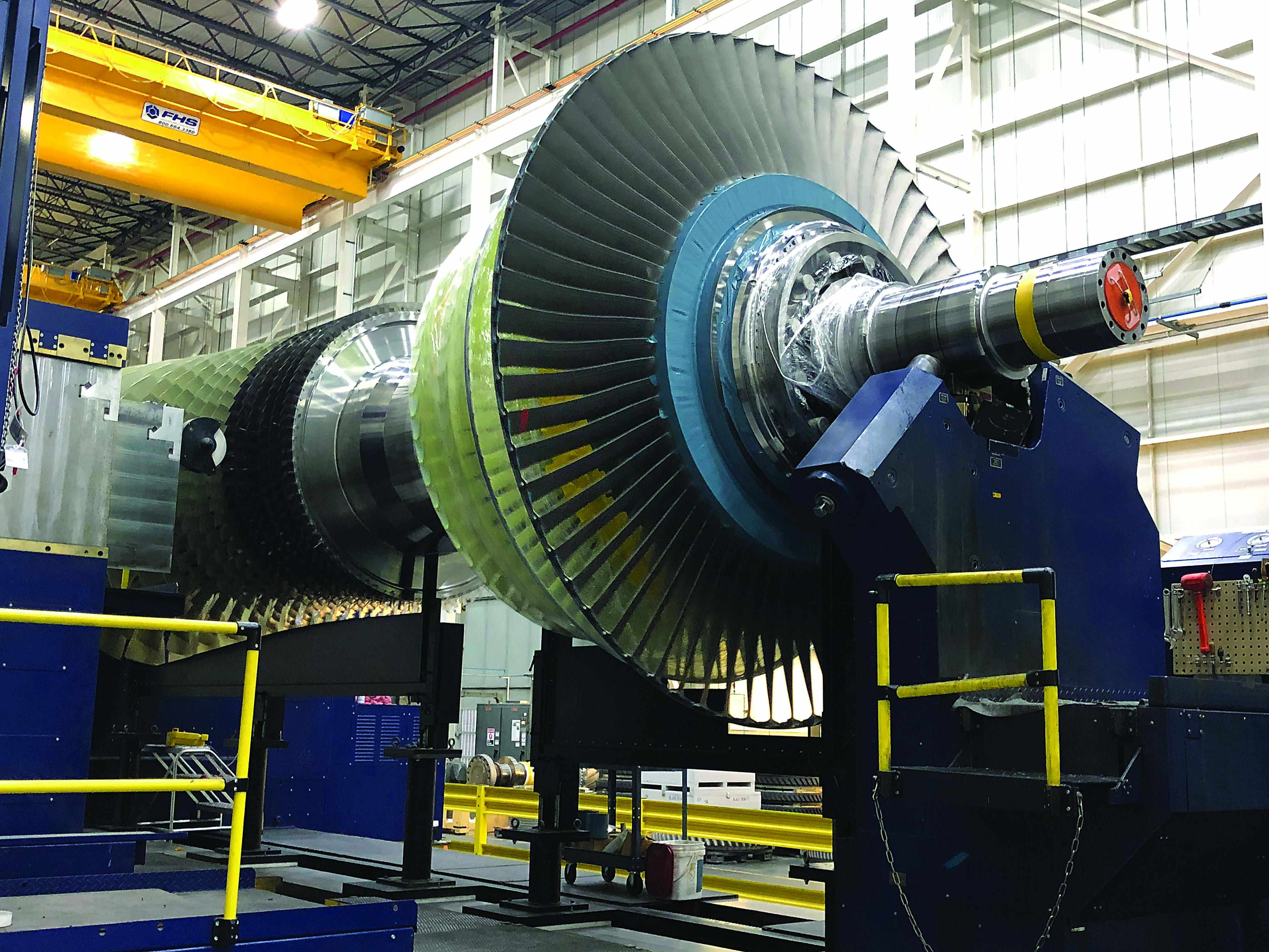
Gas turbine rotors can weigh 64 metric tons (70 tons) when fully assembled. The largest lathe at Mitsubishi Hitachi Power Systems Americas is rated at 200 metric tons (220 tons).  Image courtesy of C. Tate

Holding parts on a large horizontal boring machine is no different from holding parts on a small machining center. When we can justify the expense, we make dedicated fixtures that mount on a table and provide clamping and locating elements for a part. In other situations, it is not feasible to make a fixture, so a part is mounted directly on a machine table and clamped with T-nuts, threaded studs and strap clamps like those found with a knee mill in a toolroom.

Much like with workholding, cutting tools and toolholders used on large machines are not different from those used on small machines. Our horizontal boring machines all have CAT 50 spindles, and milling toolholders use ER-style collet chucks, hydraulic chucks and some shrink-fit holders. Many cutting tools surprisingly are small relative to the size of parts; most of our tools are 25 mm (1") or less in diameter. However, 500 mm (20") boring heads, 100 mm (4") drills and 75 mm (3") taps are not uncommon with horizontal boring machines.

Much like with milling, turning tools used on big lathes are small relative to part size. All lathes at Mitsubishi Hitachi Power Systems Americas utilize Capto C8 toolholders with various types of inserts in common shapes and sizes. With many of our parts, chatter can be a problem because lathe tools frequently have long extensions. Capto tools provide the option to use vibration damping tools, and the Capto interface gives support in multiple planes. Both features help eliminate chatter. Capto also supplies an exceptionally repeatable connection, so we do not need to remeasure tools each time they are changed.

Big parts probably have big tolerances, right? Not really. On the loose side, we are allowed ±0.15 mm (0.006"), which may sound like a lot until considering that some parts can be 3.7 m (12') tall with features 3 m (9.8') apart. On the tight side, we hold some 850 mm (33.5") shaft diameters to +0/-0.01 mm (+0/-0.0004"), which can be difficult for small parts. To achieve these tolerances, we spend large sums of money on calibration to ensure that machines are repeatable and accurate.


Casings for gas turbines are enormous. The overhead cranes are rated at 226,796 kg (500,000 lbs.) each. Image courtesy of C. Tate

Small parts are subjected to distortion from clamping, stress relieving and aggressive machining. Big parts are worse. They are subjected to the same issues but have an added challenge: weight. Large parts can distort under their own weight, causing problems like bowed shafts or out-of-round rings. Some machining processes start with a “slow roll” in which we allow a sizable shaft to rotate for an entire shift to remove a bow before we machine. In some cases, like with a ring that has a thin section relative to the diameter, we must perform stress-relieving heat-treat operations before taking a part to a machine. This prevents movement during machining operations that require big ovens. Our largest oven is 10 m (33') deep and 4 m (13') tall — almost spacious enough for a semitrailer.

Estimating cycle times is similar to estimating for small parts. To calculate cutting times, we use our CAM software the same way that a user would for small parts, but that is where similarities end. Small parts are loaded by hand, and handling times are only a few seconds. Our handling times for big parts are measured in hours. It can take two hours to flip a large cylinder and three to four hours to move a gas turbine rotor from one end of the shop to the other. It is necessary to account for all material handling or else cycle time and lead time estimates can be wrong by multiple shifts.

All in all, machining large parts on large machines is not very different from machining small parts as long as the few distinct differences are recognized. The primary difference is simply size.   


Related Glossary Terms

  • boring

    boring

    Enlarging a hole that already has been drilled or cored. Generally, it is an operation of truing the previously drilled hole with a single-point, lathe-type tool. Boring is essentially internal turning, in that usually a single-point cutting tool forms the internal shape. Some tools are available with two cutting edges to balance cutting forces.

  • boring machine

    boring machine

    Similar to a turning machine except that the cutting tool (single-point or multiple-cutting-edge), rather than the workpiece, rotates to perform internal cuts. However, boring can be accomplished by holding the tool stationary and turning the workpiece. Takes a variety of vertical, slanted and horizontal forms, and has one or more spindles. Typically a large, powerful machine, it can readily hold tolerances to 0.0001". See jig boring; lathe; turning machine.

  • calibration

    calibration

    Checking measuring instruments and devices against a master set to ensure that, over time, they have remained dimensionally stable and nominally accurate.

  • centers

    centers

    Cone-shaped pins that support a workpiece by one or two ends during machining. The centers fit into holes drilled in the workpiece ends. Centers that turn with the workpiece are called “live” centers; those that do not are called “dead” centers.

  • chatter

    chatter

    Condition of vibration involving the machine, workpiece and cutting tool. Once this condition arises, it is often self-sustaining until the problem is corrected. Chatter can be identified when lines or grooves appear at regular intervals in the workpiece. These lines or grooves are caused by the teeth of the cutter as they vibrate in and out of the workpiece and their spacing depends on the frequency of vibration.

  • chuck

    chuck

    Workholding device that affixes to a mill, lathe or drill-press spindle. It holds a tool or workpiece by one end, allowing it to be rotated. May also be fitted to the machine table to hold a workpiece. Two or more adjustable jaws actually hold the tool or part. May be actuated manually, pneumatically, hydraulically or electrically. See collet.

  • collet

    collet

    Flexible-sided device that secures a tool or workpiece. Similar in function to a chuck, but can accommodate only a narrow size range. Typically provides greater gripping force and precision than a chuck. See chuck.

  • computer-aided manufacturing ( CAM)

    computer-aided manufacturing ( CAM)

    Use of computers to control machining and manufacturing processes.

  • fixture

    fixture

    Device, often made in-house, that holds a specific workpiece. See jig; modular fixturing.

  • gang cutting ( milling)

    gang cutting ( milling)

    Machining with several cutters mounted on a single arbor, generally for simultaneous cutting.

  • lathe

    lathe

    Turning machine capable of sawing, milling, grinding, gear-cutting, drilling, reaming, boring, threading, facing, chamfering, grooving, knurling, spinning, parting, necking, taper-cutting, and cam- and eccentric-cutting, as well as step- and straight-turning. Comes in a variety of forms, ranging from manual to semiautomatic to fully automatic, with major types being engine lathes, turning and contouring lathes, turret lathes and numerical-control lathes. The engine lathe consists of a headstock and spindle, tailstock, bed, carriage (complete with apron) and cross slides. Features include gear- (speed) and feed-selector levers, toolpost, compound rest, lead screw and reversing lead screw, threading dial and rapid-traverse lever. Special lathe types include through-the-spindle, camshaft and crankshaft, brake drum and rotor, spinning and gun-barrel machines. Toolroom and bench lathes are used for precision work; the former for tool-and-die work and similar tasks, the latter for small workpieces (instruments, watches), normally without a power feed. Models are typically designated according to their “swing,” or the largest-diameter workpiece that can be rotated; bed length, or the distance between centers; and horsepower generated. See turning machine.

  • machining center

    machining center

    CNC machine tool capable of drilling, reaming, tapping, milling and boring. Normally comes with an automatic toolchanger. See automatic toolchanger.

  • milling

    milling

    Machining operation in which metal or other material is removed by applying power to a rotating cutter. In vertical milling, the cutting tool is mounted vertically on the spindle. In horizontal milling, the cutting tool is mounted horizontally, either directly on the spindle or on an arbor. Horizontal milling is further broken down into conventional milling, where the cutter rotates opposite the direction of feed, or “up” into the workpiece; and climb milling, where the cutter rotates in the direction of feed, or “down” into the workpiece. Milling operations include plane or surface milling, endmilling, facemilling, angle milling, form milling and profiling.

  • milling machine ( mill)

    milling machine ( mill)

    Runs endmills and arbor-mounted milling cutters. Features include a head with a spindle that drives the cutters; a column, knee and table that provide motion in the three Cartesian axes; and a base that supports the components and houses the cutting-fluid pump and reservoir. The work is mounted on the table and fed into the rotating cutter or endmill to accomplish the milling steps; vertical milling machines also feed endmills into the work by means of a spindle-mounted quill. Models range from small manual machines to big bed-type and duplex mills. All take one of three basic forms: vertical, horizontal or convertible horizontal/vertical. Vertical machines may be knee-type (the table is mounted on a knee that can be elevated) or bed-type (the table is securely supported and only moves horizontally). In general, horizontal machines are bigger and more powerful, while vertical machines are lighter but more versatile and easier to set up and operate.

  • stress relieving

    stress relieving

    Annealing designed to relieve internal stresses caused by machining, welding, casting, cold working, quenching or normalizing.

  • toolroom lathe

    toolroom lathe

    High-precision lathe built to hold tighter tolerances than regular, general-purpose lathes can hold. See lathe; turning machine.

  • turning

    turning

    Workpiece is held in a chuck, mounted on a face plate or secured between centers and rotated while a cutting tool, normally a single-point tool, is fed into it along its periphery or across its end or face. Takes the form of straight turning (cutting along the periphery of the workpiece); taper turning (creating a taper); step turning (turning different-size diameters on the same work); chamfering (beveling an edge or shoulder); facing (cutting on an end); turning threads (usually external but can be internal); roughing (high-volume metal removal); and finishing (final light cuts). Performed on lathes, turning centers, chucking machines, automatic screw machines and similar machines.