Because high-speed steel inserts can bend without breaking, they are an effective choice for select applications.
To cut a long story short, the advent of carbide as an effective cutting tool material caused HSS to become continuously less popular as a tool material. When appropriate, tool designers developed tool bodies to accept throwaway carbide inserts and enable machining with carbide cutting edges while reducing tool costs. But HSS’ bend-strength toughness compared to carbide’s harder and more brittle characteristics still offers advantages in some applications, and rather than always applying solid-HSS tools, the same bodies for carbide inserts accept HSS ones as well.
Interrupted cutting is one area where HSS offers an advantage, according to Ken King, CEO of THINBIT/Kaiser Tool Co. Inc., Ft. Wayne, Ind. The toolmaker offers standard HSS inserts for grooving, face grooving, threading and parting, as well as specials. Compared to carbide, “high-speed steel will take a lot more abuse as far as flexing and interrupted cuts,” he said. “If you do crash high-speed steel, sometimes you’ll see the inserts are actually bent or flexed. You can use that to your advantage if the application is so bad that you require the tool to bend a little bit.”
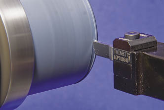
Courtesy of THINBIT/Kaiser Tool
Parting is performed using a HSS insert from THINBIT.
Harder tool materials, such as carbide, don’t like to bend. King used the analogy of glass and wood to compare and contrast the material properties of carbide and HSS. “You’re not going to bend a piece of glass; it’s going to break and shatter,” he said. “Whereas wood will shatter eventually, it will bend more than glass.”
Cutters tooled with HSS inserts are also suitable when machining with less-than-optimal rigidity. “High-speed steel inserts are for machining at a lower cutting speed where high toughness is required for application under unfavorable machining conditions,” said Hellmut R. Ross, president of Arno Rouse USA LLC, Harvard, Ill., which supplies HSS inserts among other tools. “I wouldn’t say the machine, but the setup might not be that rigid.”
Speed Limit
Once upon a time, HSS tools were applied for “high-speed machining,” but that’s no longer the case. In applications where carbide inserts are able to run at 300 sfm, the recommended cutting speed for HSS inserts is about 60 sfm, according to Mike Warner, president of Arthur R. Warner Co., Latrobe, Pa., which specializes in producing HSS inserts. “High-speed steel should be called slow-speed steel, but it’s amazing some of the speeds you can run,” he said. “We have some high-speed steel in applications running up to 125 sfm with coatings.”
Warner added that when a machine tool, particularly an older one, does not have an adequate spindle speed to achieve the required surface footage to cut efficiently with carbide, HSS is the material of choice. “You have to slow down a little bit but your tool is going to last a lot longer and you’re going to get more parts per tool,” he said, adding that the chip load can be larger when cutting with HSS inserts vs. carbide inserts.
King concurred that HSS inserts cut slower relative to the same workpiece material. For example, HSS inserts can machine Teflon, or polytetrafluoroethylene, at 250 sfm with a 0.003-ipr feed rate compared to 400 sfm with a 0.003 ipr for carbide inserts, according to THINBIT. For one Teflon application, THINBIT engineered a special HSS insert design with a 60° top rake. “That gives a huge upsharp angle to help peel the Teflon away,” King said.
Ross noted that the lower machining parameters for HSS inserts, which he estimated are about half of the recommended parameters for carbide, make them suitable for machining plastics. Other suitable workpiece materials include aluminum, wrought and cast alloys, nickel alloys, copper, brass, bronze “and the outside skin on a forged part, which is really difficult to machine,” he said.
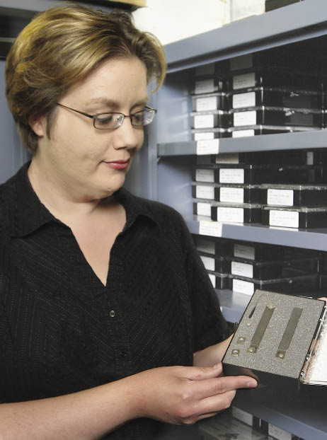
Courtesy of Bill Kennedy
Jennifer Warner, vice president of operations for Arthur R. Warner Co. (above), examines a HSS insert turning kit, containing five CCMW-3-2.5-2 screw-on, 7° positive, 0.031 " radius inserts; left- and right-hand ½ "-shank tool bodies; insert screws; and a wrench. The left-hand tool body has two pockets, with the second one providing a 50° side-cutting edge angle. Top photo: A selection of the company’s application-specific HSS special inserts.
Keen Cutting
Plastics are difficult to cut because they are typically gummy and tend to melt, burn and adhere to the cutting tool. HSS’ toughness enables toolmakers to produce inserts with a keen edge that has minimal edge preparation to reduce heat and friction at the tool/workpiece interface. “It’s a razor sharp cutting edge,” Ross said.
Warner explained that the depth of an edge preparation, such as a T- or K-land, on a carbide insert equals the minimum DOC the insert can effectively take. “If it’s an 0.008 " hone on an insert, you can’t take a 0.006 " depth of cut,” he said. “It would generate so much heat that your tool life would deteriorate.”
Although edge preps to minimize chipping aren’t required on HSS inserts, the inserts can have chipbreakers to enhance chip control. “Our standard chipbreaker is a 10°, 0.090 " effective-width chipbreaker, which 90 percent of the time will work sufficiently,” Warner said.
He added that, in addition to controlling chip size and the direction chips travel, the chipbreaker creates a double-positive cutting configuration to reduce heat at the tool/workpiece interface and impart a finer surface finish. As previously noted, tool bodies that accept carbide inserts also hold HSS ones, but not all bodies will work equally well. “A lot of people will buy a high-speed steel insert and put it into a negative carbide holder and it won’t work,” Warner said. “We watch that very closely whenever we’re matching high-speed steel to holders for carbide inserts.”
Recommended starting-point speeds and feeds for grooving with HSS (grade M-2).
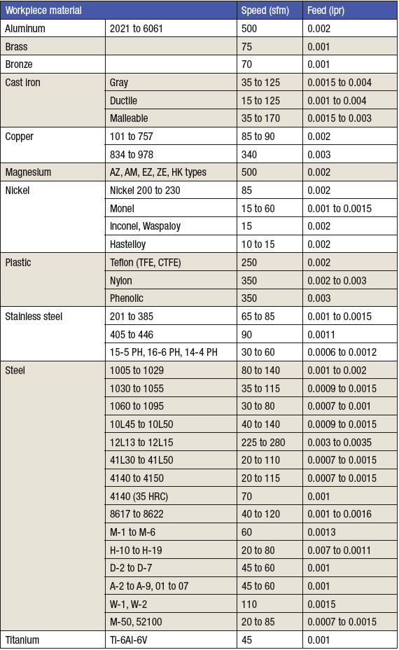
Source: THINBIT/Kaiser Tool
Because many carbide inserts have a negative clearance on the insert’s periphery, Warner noted that when end users position the insert 7° forward to provide relief on the insert edge, but without a chipbreaker, it creates a negative cutting configuration on the top. That generates a lot of heat and—like carbide—heat is no friend to HSS.
Sometimes, it’s beneficial to put carbide and HSS inserts into the same tool body, such as a combination cutter for turning a 12 "-dia. part that requires its center to be bored. “On older machines, you can’t change the machine’s rpm during a cut, so the OD of that part has the correct surface feet for carbide but the middle of the part is hardly turning,” Warner said. “They will use high-speed steel in the middle and carbide on the outside.”
When coated, the coating must be deposited at a temperature that’s not too high to temper HSS, which causes it to loose its hardness. Therefore, HSS inserts must be PVD coated, where the deposition process takes place at 350° to 900° F compared to 1,800° to 2,000° F for the CVD process. The same coatings found on carbide inserts, such as TiN, TiCN and AlTiN, are available on HSS inserts. Although coated HSS inserts can cut at higher speeds and feeds than uncoated ones, Warner noted that only a small percentage of the HSS inserts his company sells are coated. “Shops don’t try high-speed steel unless they’re having a particular problem with carbide and usually 10 uncoated inserts gets them out of the problem,” he said. “Eighty percent of my customers buy fewer than 50 inserts.”
Warner added that if a customer needs more HSS inserts beyond the initial order, the subsequent ones are typically coated. For example, one of his customers was having a problem milling plastics with carbide and found that a HSS insert worked well. “In the next go-around, we coated it and it worked extremely well, so now that company regularly buys coated high-speed steel inserts,” he said.
Material Matters
Warner pointed out that HSS inserts are effective for cutting gummy and workhardening materials because “HSS actually cuts the material where carbide is meant to fracture it in front of the cut.” He added that, in some applications, HSS is able to impart a finer surface finish than carbide. “High-speed steel cuts it; it doesn’t tear it.”
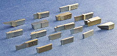
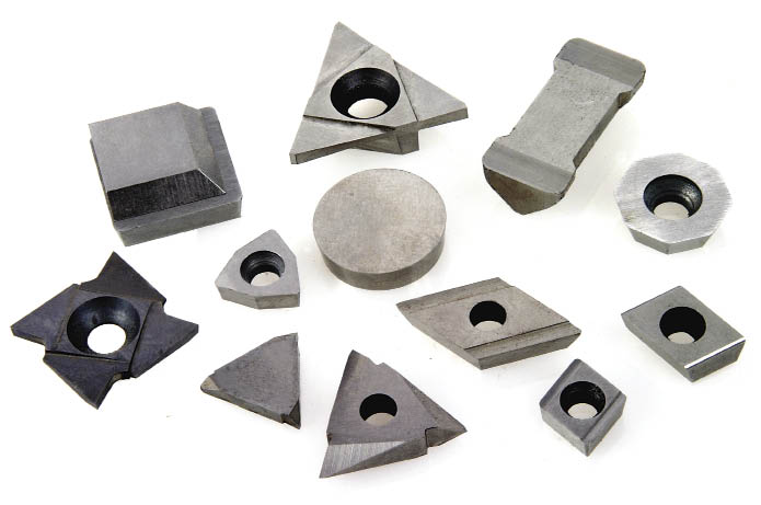
Courtesy of THINBIT/Kaiser Tool
A selection of HSS inserts from THINBIT.
To enhance HSS’ toughness while increasing its hardness, HSS producer Erasteel Inc., Boonton, N.J., is producing P/M HSS with higher alloy content, according to Oscar Lundvall, the company’s business developer. That includes alloying the material with niobium, such as for Erasteel’s ASP 2055-grade P/M HSS with about 2 percent niobium. “The powder steel is very homogenous in its structure, but with the niobium alloying we achieve even finer dispersion of carbides, which gives us a material that is even tougher than a similar steel without niobium,” he said. “It is easier to grind and produce a surface finish that is much finer than ordinary P/M steel.”
Other alloying elements in HSS include chromium, vanadium, tungsten, molybdenum and cobalt. Unlike cemented tungsten carbide, cobalt is not used as a binder in HSS but rather as an alloying element that’s melted with the base steel and other elements and then atomized into the finished composition. “You’re not mixing powders like with tungsten carbide,” Lundvall said. “It’s a totally different process.”
Lundvall noted that applications exist where HSS, in general, outperforms carbide because HSS’ higher toughness is more forgiving and its sharper cutting edges prove more effective. “One good area is milling high-strength titanium, such as the new titanium 555-3 alloy where we’ve seen some spectacular results with a coated high-cobalt ASP 2060 special endmill compared to carbides,” he said.
HSS also has the advantage of costing less than carbide, but that doesn’t necessarily translate into HSS inserts costing less than comparable carbide ones. Arno Rouse offers a TiN-coated carbide TCFT insert for $10 and the same one made of HSS is $37.35. “You have to get a lot more parts to justify that,” Ross said.
THINBIT, however, charges the same price for its standard HSS and carbide inserts, according to King, even though producing HSS ones requires a longer cycle time. He noted that all THINBIT HSS inserts are made of M-2 conventional HSS.
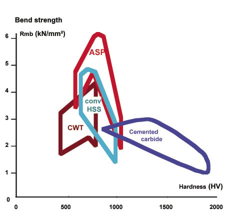
Courtesy of Erasteel
A comparison of the toughness (as measured in bend strength) and hardness for Erasteel’s ASP-grade P/M HSS, conventional tool steel (CWT), conventional HSS and cemented carbide.
Arthur R. Warner doesn’t offer carbide inserts, but Warner said its HSS inserts range from $4 to about $15, depending on type and quantity. As a comparison, he noted that a high-quality TNMC32NV carbide threading insert costs about $7. “Ours are $12, but there are 38 operations on that insert to make it and it will last a lot longer than carbide in quite a few applications,” Warner said. He added that at least until 2 years ago, his research indicated that 30 percent of milling in the U.S. is still performed with HSS tools, including inserts and round tools.
Recently, cutting tool sales have been down across the board, but King indicated there’s a fairly healthy demand for HSS inserts. “When we add new products, we consider whether to offer it in high-speed steel or not,” he said. “It’s a material we still consider active and not obsolete or discontinued. We know it solves problems for people.” CTE
About the Author: Alan Richter is editor of Cutting Tool Engineering, having joined the publication in 2000. Contact him at (847) 714-0175 or [email protected].
Making HSS inserts
Similar to producing HSS, making HSS inserts is significantly different from producing carbide ones, which start as a powder that’s sintered into shape. “They press a carbide insert and—bang—they got the hole, the chipbreaker and everything they need right there,” said Arthur R. Warner Co.’s Mike Warner.
He explained that his company starts with a sheet of HSS and uses an abrasive waterjet machine to create insert profiles. For the 90 percent of the inserts that are held with screws, the toolmaker then drills a hole and creates a countersink for the setscrew. Finishing involves grinding all surfaces.
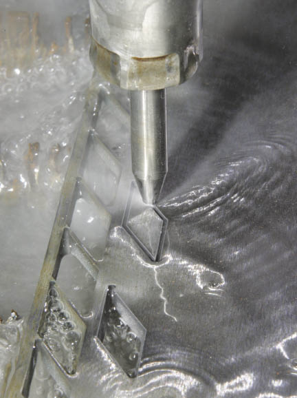
Courtesy of Bill Kennedy
Arthur R. Warner Co. waterjet machines a 35° triangle, T-15 HSS insert blank.
When finishing the periphery of screw-on inserts, Warner said the company locates the periphery off of the countersink instead of the hole to ensure accuracy. “The hole is not what centers the insert in the pocket, the countersink is,” he said.
Not only do HSS inserts run slower in a machine tool, they take longer to grind than carbide ones. Ken King of THINBIT/Kaiser Tool Co. Inc. said that’s because a grinding wheel appropriate for HSS tends to push the insert as it is grinding. “You have to cut a little slower so the insert won’t flex away from the wheel and leave material you wanted to remove,” he said.
Even with the highest-quality HSS, toolmakers have to be cautious when grinding the material—especially finish grinding—to produce good tools, according to Oscar Lundvall of Erasteel Inc. “If you do a bad grinding operation, you’ll have big scratches or grinding burn on the surface and that’ll work as a defect, so it might break,” he said, adding that the same applies to making carbide tools.
—A. Richter
Contributors
Arno Rouse USA LLC
(800) 943-4426
www.arno-rouse.com
Arthur R. Warner Co.
(724) 539-9229
www.arwarnerco.com
Erasteel Inc.
(973) 335-8400
www.erasteel.com
THINBIT/Kaiser Tool Co. Inc.
(888) THINBIT
www.thinbit.com
Related Glossary Terms
- abrasive
abrasive
Substance used for grinding, honing, lapping, superfinishing and polishing. Examples include garnet, emery, corundum, silicon carbide, cubic boron nitride and diamond in various grit sizes.
- abrasive waterjet ( AWJ)
abrasive waterjet ( AWJ)
System that uses high-pressure waterjets in combination with a slurry of fine abrasive grains to machine materials. See waterjet cutting.
- alloying element
alloying element
Element added to a metal to change its mechanical and/or physical properties.
- alloys
alloys
Substances having metallic properties and being composed of two or more chemical elements of which at least one is a metal.
- cast alloys
cast alloys
Alloys cast from the molten state. Most high-speed steel is melted in an electric-arc furnace and cast into ingots.
- centers
centers
Cone-shaped pins that support a workpiece by one or two ends during machining. The centers fit into holes drilled in the workpiece ends. Centers that turn with the workpiece are called “live” centers; those that do not are called “dead” centers.
- chemical vapor deposition ( CVD)
chemical vapor deposition ( CVD)
High-temperature (1,000° C or higher), atmosphere-controlled process in which a chemical reaction is induced for the purpose of depositing a coating 2µm to 12µm thick on a tool’s surface. See coated tools; PVD, physical vapor deposition.
- chipbreaker
chipbreaker
Groove or other tool geometry that breaks chips into small fragments as they come off the workpiece. Designed to prevent chips from becoming so long that they are difficult to control, catch in turning parts and cause safety problems.
- clearance
clearance
Space provided behind a tool’s land or relief to prevent rubbing and subsequent premature deterioration of the tool. See land; relief.
- countersink
countersink
Tool that cuts a sloped depression at the top of a hole to permit a screw head or other object to rest flush with the surface of the workpiece.
- cutting speed
cutting speed
Tangential velocity on the surface of the tool or workpiece at the cutting interface. The formula for cutting speed (sfm) is tool diameter 5 0.26 5 spindle speed (rpm). The formula for feed per tooth (fpt) is table feed (ipm)/number of flutes/spindle speed (rpm). The formula for spindle speed (rpm) is cutting speed (sfm) 5 3.82/tool diameter. The formula for table feed (ipm) is feed per tooth (ftp) 5 number of tool flutes 5 spindle speed (rpm).
- depth of cut
depth of cut
Distance between the bottom of the cut and the uncut surface of the workpiece, measured in a direction at right angles to the machined surface of the workpiece.
- edge preparation
edge preparation
Conditioning of the cutting edge, such as a honing or chamfering, to make it stronger and less susceptible to chipping. A chamfer is a bevel on the tool’s cutting edge; the angle is measured from the cutting face downward and generally varies from 25° to 45°. Honing is the process of rounding or blunting the cutting edge with abrasives, either manually or mechanically.
- endmill
endmill
Milling cutter held by its shank that cuts on its periphery and, if so configured, on its free end. Takes a variety of shapes (single- and double-end, roughing, ballnose and cup-end) and sizes (stub, medium, long and extra-long). Also comes with differing numbers of flutes.
- feed
feed
Rate of change of position of the tool as a whole, relative to the workpiece while cutting.
- gang cutting ( milling)
gang cutting ( milling)
Machining with several cutters mounted on a single arbor, generally for simultaneous cutting.
- grinding
grinding
Machining operation in which material is removed from the workpiece by a powered abrasive wheel, stone, belt, paste, sheet, compound, slurry, etc. Takes various forms: surface grinding (creates flat and/or squared surfaces); cylindrical grinding (for external cylindrical and tapered shapes, fillets, undercuts, etc.); centerless grinding; chamfering; thread and form grinding; tool and cutter grinding; offhand grinding; lapping and polishing (grinding with extremely fine grits to create ultrasmooth surfaces); honing; and disc grinding.
- grinding wheel
grinding wheel
Wheel formed from abrasive material mixed in a suitable matrix. Takes a variety of shapes but falls into two basic categories: one that cuts on its periphery, as in reciprocating grinding, and one that cuts on its side or face, as in tool and cutter grinding.
- grooving
grooving
Machining grooves and shallow channels. Example: grooving ball-bearing raceways. Typically performed by tools that are capable of light cuts at high feed rates. Imparts high-quality finish.
- hardness
hardness
Hardness is a measure of the resistance of a material to surface indentation or abrasion. There is no absolute scale for hardness. In order to express hardness quantitatively, each type of test has its own scale, which defines hardness. Indentation hardness obtained through static methods is measured by Brinell, Rockwell, Vickers and Knoop tests. Hardness without indentation is measured by a dynamic method, known as the Scleroscope test.
- high-speed steels ( HSS)
high-speed steels ( HSS)
Available in two major types: tungsten high-speed steels (designated by letter T having tungsten as the principal alloying element) and molybdenum high-speed steels (designated by letter M having molybdenum as the principal alloying element). The type T high-speed steels containing cobalt have higher wear resistance and greater red (hot) hardness, withstanding cutting temperature up to 1,100º F (590º C). The type T steels are used to fabricate metalcutting tools (milling cutters, drills, reamers and taps), woodworking tools, various types of punches and dies, ball and roller bearings. The type M steels are used for cutting tools and various types of dies.
- lapping compound( powder)
lapping compound( powder)
Light, abrasive material used for finishing a surface.
- milling
milling
Machining operation in which metal or other material is removed by applying power to a rotating cutter. In vertical milling, the cutting tool is mounted vertically on the spindle. In horizontal milling, the cutting tool is mounted horizontally, either directly on the spindle or on an arbor. Horizontal milling is further broken down into conventional milling, where the cutter rotates opposite the direction of feed, or “up” into the workpiece; and climb milling, where the cutter rotates in the direction of feed, or “down” into the workpiece. Milling operations include plane or surface milling, endmilling, facemilling, angle milling, form milling and profiling.
- outer diameter ( OD)
outer diameter ( OD)
Dimension that defines the exterior diameter of a cylindrical or round part. See ID, inner diameter.
- parting
parting
When used in lathe or screw-machine operations, this process separates a completed part from chuck-held or collet-fed stock by means of a very narrow, flat-end cutting, or parting, tool.
- physical vapor deposition ( PVD)
physical vapor deposition ( PVD)
Tool-coating process performed at low temperature (500° C), compared to chemical vapor deposition (1,000° C). Employs electric field to generate necessary heat for depositing coating on a tool’s surface. See CVD, chemical vapor deposition.
- rake
rake
Angle of inclination between the face of the cutting tool and the workpiece. If the face of the tool lies in a plane through the axis of the workpiece, the tool is said to have a neutral, or zero, rake. If the inclination of the tool face makes the cutting edge more acute than when the rake angle is zero, the rake is positive. If the inclination of the tool face makes the cutting edge less acute or more blunt than when the rake angle is zero, the rake is negative.
- relief
relief
Space provided behind the cutting edges to prevent rubbing. Sometimes called primary relief. Secondary relief provides additional space behind primary relief. Relief on end teeth is axial relief; relief on side teeth is peripheral relief.
- threading
threading
Process of both external (e.g., thread milling) and internal (e.g., tapping, thread milling) cutting, turning and rolling of threads into particular material. Standardized specifications are available to determine the desired results of the threading process. Numerous thread-series designations are written for specific applications. Threading often is performed on a lathe. Specifications such as thread height are critical in determining the strength of the threads. The material used is taken into consideration in determining the expected results of any particular application for that threaded piece. In external threading, a calculated depth is required as well as a particular angle to the cut. To perform internal threading, the exact diameter to bore the hole is critical before threading. The threads are distinguished from one another by the amount of tolerance and/or allowance that is specified. See turning.
- titanium carbonitride ( TiCN)
titanium carbonitride ( TiCN)
Often used as a tool coating. See coated tools.
- titanium nitride ( TiN)
titanium nitride ( TiN)
Added to titanium-carbide tooling to permit machining of hard metals at high speeds. Also used as a tool coating. See coated tools.
- tungsten carbide ( WC)
tungsten carbide ( WC)
Intermetallic compound consisting of equal parts, by atomic weight, of tungsten and carbon. Sometimes tungsten carbide is used in reference to the cemented tungsten carbide material with cobalt added and/or with titanium carbide or tantalum carbide added. Thus, the tungsten carbide may be used to refer to pure tungsten carbide as well as co-bonded tungsten carbide, which may or may not contain added titanium carbide and/or tantalum carbide.
- turning
turning
Workpiece is held in a chuck, mounted on a face plate or secured between centers and rotated while a cutting tool, normally a single-point tool, is fed into it along its periphery or across its end or face. Takes the form of straight turning (cutting along the periphery of the workpiece); taper turning (creating a taper); step turning (turning different-size diameters on the same work); chamfering (beveling an edge or shoulder); facing (cutting on an end); turning threads (usually external but can be internal); roughing (high-volume metal removal); and finishing (final light cuts). Performed on lathes, turning centers, chucking machines, automatic screw machines and similar machines.
- workhardening
workhardening
Tendency of all metals to become harder when they are machined or subjected to other stresses and strains. This trait is particularly pronounced in soft, low-carbon steel or alloys containing nickel and manganese—nonmagnetic stainless steel, high-manganese steel and the superalloys Inconel and Monel.
Author

Alan holds a bachelor’s degree in journalism from Southern Illinois University Carbondale. Including his 20 years at CTE, Alan has more than 30 years of trade journalism experience.