Traditional roughing passes are characterized by taking a series of offset radial passes. With this approach, regardless of the offset step-over value used, the tool will experience increased engagement at every internal corner and when driving into slots. These corners and slots are where cutting forces spike and when the tool is most prone to breakage.
To operate at a high feed rate while roughing with traditional strategies, the programmer must instruct the tool to take a shallow axial DOC. This approach overemphasizes cutting with the bottom of the tool rather than using the whole flute length. In this case, the tool stores more heat at the bottom, causing premature wear, instead of spreading heat along the entire flute length.
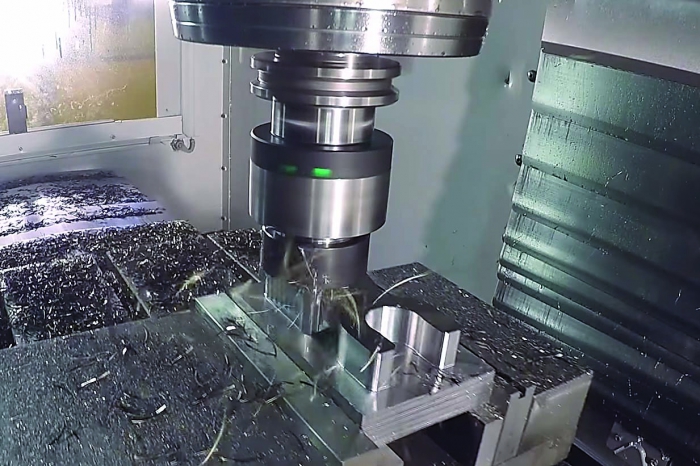
Adaptive clearing maintains a constant radial tool engagement throughout the cut, eliminating spikes in cutting forces. Image courtesy of Autodesk.
In contrast, maintaining constant cutting forces provides a constant radial tool engagement throughout the entire cut, which eliminates spikes in the cutting forces. This approach allows the programmer to take a larger axial DOC while simultaneously maintaining a high feed rate and extending tool life.
In traditional roughing, the machine operator needs to lower the feed rate to avoid the worst-case scenario: breaking a tool while in a corner or slot, where forces spike. However, this means that for the rest of the roughing operation, the program is not running at optimal material-removal rates.
By maintaining constant cutting forces, an end user quickly reaches the most efficient machining rate and maintains that rate throughout the cut, then repositions for the next cut. This method—called adaptive clearing—allows milling at an efficient rate during all cuts, with constant cutting forces throughout a cut. Constant forces mean fewer vibrations in the tool and less shock to the cutting edges caused by those vibrations. This extends tool life.
Because the tool spends more time cutting at maximum efficiency, the time span of the entire cut is shorter. When both the traditional and adaptive clearing methods were tested recently by Autodesk Inc., the traditional roughing pass consumed 8:09 minutes, while the adaptive-clearing technique took only 2:01 minutes.
By reducing the radial DOC, users can increase the tool flute count and the mrr. They can then use chip-thinning calculations to increase the feed rate and maintain the proper chip thickness. A thicker chip pulls more heat away from the tool.
Without spikes in material-removal rates, setting feed rates for maximum material removal becomes much easier. Use the data from a tool supplier or simply start milling and slowly increase the feed rate to a comfortable level.
Adaptive-clearing strategies are easy to implement and test because they don’t require special tools or a special milling machine; they work well on entry-level mills and the fastest high-performance mills. In addition, they are available for a wide range of CAD systems.
Contact Details
Related Glossary Terms
- computer-aided design ( CAD)
computer-aided design ( CAD)
Product-design functions performed with the help of computers and special software.
- feed
feed
Rate of change of position of the tool as a whole, relative to the workpiece while cutting.
- gang cutting ( milling)
gang cutting ( milling)
Machining with several cutters mounted on a single arbor, generally for simultaneous cutting.
- milling
milling
Machining operation in which metal or other material is removed by applying power to a rotating cutter. In vertical milling, the cutting tool is mounted vertically on the spindle. In horizontal milling, the cutting tool is mounted horizontally, either directly on the spindle or on an arbor. Horizontal milling is further broken down into conventional milling, where the cutter rotates opposite the direction of feed, or “up” into the workpiece; and climb milling, where the cutter rotates in the direction of feed, or “down” into the workpiece. Milling operations include plane or surface milling, endmilling, facemilling, angle milling, form milling and profiling.
- step-over
step-over
Distance between the passes of the toolpath; the path spacing. The distance the tool will move horizontally when making the next pass. Too great of a step-over will cause difficulty machining because there will be too much pressure on the tool as it is trying to cut with too much of its surface area.
—Adapted from the article “Speed up your milling with constant cutter forces” by Autodesk Inc., San Rafael, Calif., at www.autodesk.com. The original article is at tinyurl.com/autodesk-constant.