Researchers have developed cost-effective strategies for achieving maximum material-removal rates in ceramic machining.
Technical ceramics such as silicon nitride, silicon carbide, alumina, and zirconia have great potential as structural materials due to their light weight, resistance to wear and high-temperature deformation, and other superior characteristics over metallic materials. However, the high cost associated with machining technical ceramics continues to be the limiting factor in the acceptance and use of these materials. Machining costs have been estimated to be as high as 50% of the total cost of the component.
The high cost results, primarily, from a lack of cost-effective methods of machining ceramics. Most ceramic components for structural applications require finish machining to achieve tight dimensional tolerances and a good surface finish. Grinding with diamond wheels has been the most widely used finishing technique. The rotating diamond wheel removes material stock while fluid is introduced to the grinding zone for lubricating, cooling, and flushing the work surface and the wheel.
Given the fact that, during the grinding process, the grinding-zone temperatures are high and the geometry of the diamond grits on the wheel surface is constantly changing, the actual interactions between the wheel and the workpiece are quite complicated and difficult to predict, yet it needs to be better understood.
The interactions are mechanical, thermal, and chemical in nature. These interactions not only remove stock as intended but also affect the surface of the workpiece and the diamond wheel. Damage in the form of residual stress, microcracks, and even phase transformation often results, depending on material characteristics. Grinding also alters the wheel’s grinding performance by wearing and dulling the abrasive.
To grind ceramic components cost-effectively and with little damage to the workpiece, operators must know the characteristics of the material, the diamond wheel, and the coolant, as well as how stresses will be distributed in the part when it is in use. Understanding the influence of such process parameters as wheel speed, work speed, and depth of cut (DOC) is equally important. Using conventional machining technology, shops cannot afford to limit themselves to conservative process parameters in the hope of eliminating machining-induced damage. However, by adapting their machining practices to the application they can minimize the influence of machining damage on the function of the component.
Adapt the Process to the Material
Many different technical ceramics and composites are now commercially available. They have distinct thermal, mechanical, and electrical properties for various commercial applications. Years of ceramic-machining experience have proven that some ceramics can be ground much faster than others. However, there is no correlation between the machining characteristics of a ceramic and its published properties. A shop cannot predict a ceramic’s machinability even if it knows the material’s hardness, fracture toughness, flexural strength, elastic modulus, and thermal conductivity.
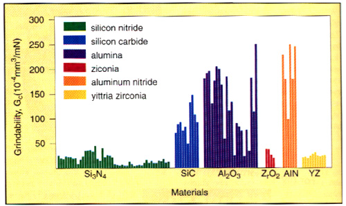 |
| Fig 1: Grindability of various ceramics. |
A ceramic-grindability test system has been developed that provides quantitative measurement of a machining characteristic called "grindability." Grindability is a specific characteristic of ceramic materials and is measured in terms of a normalized material-removal rate (mrr).
As can be seen in Figure 1, the results that have been obtained with the grindability test system indicate that within a family of material, such as silicon nitride (Si3N4), there is a wide variation in grindability. It is not entirely impossible to predict the grindability of a given ceramic before the grinding operation begins, however. While grindability measurements do not correlate with material properties or composition, they do correlate well with surface-grinding parameters such as normal force and specific energy. From these tests it can be deduced that ceramics of higher grindability require lower specific energy and grinding force.
By using the information obtained from a grindability test, a shop can choose the correct diamond-wheel and process parameters for grinding a specific ceramic material. For example, a ceramic such as Al2O3, which scores high on the grindability test, can be machined at a higher mrr than a ceramic with lower grindability such as Si3N4.
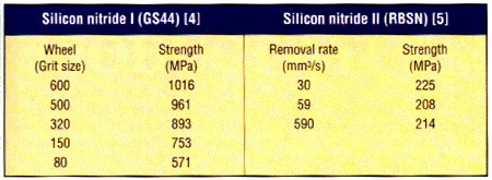 |
| Table 1: Ceramics have different sensitivity to maching conditions. |
The maximum mrr, however, can sometimes be limited by factors such as part geometry and the material’s susceptibility to machining-induced damage. Generally, ceramics with large internal flaws are less sensitive to machining-induced damage than ceramics with small internal flaws. This is illustrated in Table 1, where the strength of the hot-pressed Si3N4 (a high-strength ceramic) is much more sensitive to machining conditions than the reaction-bonded Si3N4 (a low-strength ceramic). Because of such limitations and variations, all ceramics must be tested to establish maximum grinding rates.
In determining the optimal mrr for ceramic machining, a shop must consider other factors in addition to grindability and the characteristics of the material. Among these factors are the characteristics of the grinding wheel. The performance of a diamond wheel depends on many attributes, including diamond type, grit size, concentration, bond type, and hardness. Diamond-wheel manufacturers combine these parameters in various ways to produce wheels with a wide range of performance characteristics. Wheels are usually chosen based on job requirements such as material, geometry, and surface finish.
Understand Wheel Behavior
Diamond wheels are generally identified by their diamond type (synthetic or natural), grit size, concentration (volume of diamond per volume of bond), bond type (resin, metal, or vitrified), and other qualitative designations such as the relative hardness of the bond. Diamond-wheel manufacturers vary widely in the way they calculate their wheels’ concentration. Some manufacturers allow for dimensional oversize requirements and state "true" concentration. Manufacturers that do not allow for dimensional oversize state their wheels’ concentrations as "nominal" values. The information about the diamond abrasive provided by the wheel manufacturer in its specifications refers only to the grit size. The specifications do not provide any information about the diamond’s strength, shape (cutting ability), or wear characteristics. The strength of diamond pArticles in an aggregate is usually measured in terms of friability: The lower the friability, the weaker the diamond.
Bond systems vary in their performance. For example, resin-bond diamond wheels made by different manufacturers have different hardnesses, wear characteristics, and diamond-encapsulating strengths. For this reason, a shop cannot predict a wheel’s performance simply on the basis of the wheel’s bond system.
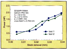 |
| Fig 2: Power rises significantly after short periods of grinding. |
Because of the variations in the manufacturing of diamond wheels, wheels of similar, and often identical, specifications made by two different manufacturers probably will not behave the same way when grinding ceramics. This variability can be seen in Figure 2, which compares the electrical-power draw of two diamond wheels that have the same specifications but are supplied by two different vendors. Under the same grinding conditions, one wheel consumes much more power than the other. As shown by the rapid increase in the draw of power, the grinding performance of the one wheel was inefficient and decreased with continued use.
To renew a wheel’s performance, a user will typically dress the wheel surface with an abrasive stick. The frequency of dressing required for a given wheel determines the cost-effectiveness of the process. By monitoring the electrical-power draw, a user can initiate wheel dressing at an optimal frequency.
To machine ceramics cost-effectively, a shop must also understand how parameters such as wheel speed, work speed, and DOC affect the grinding process. Given the fact that irregularly shaped diamonds are randomly distributed on the wheel surface and protrude unevenly from the bond matrix, quantitative characterization of the interaction between each diamond and the workpiece is difficult. For qualitative analysis, however, the following equation has proven helpful:
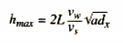
Here, hmax is the maximum uncut-chip thickness; L is the distance between consecutive cutting points, which is related to the grit size, diamond type, and concentration; vw is the work speed; vs is the wheel speed; a is the wheel DOC; and ds is the wheel diameter. Quantitatively, hmax characterizes the depth of penetration of a diamond into the workpiece when it is engaged in cutting.
In general, a smaller uncut-chip thickness is desirable to generate a smoother surface, which helps reduce machining-induced damage. However, most shops will also want to grind the workpiece in the most cost-effective manner, and this will require a high mrr. To achieve a high mrr, a higher value of the product of the work speed and the wheel DOC, or (avw), is necessary. This in turn makes the uncut-chip thickness larger. In other words, grinding with a high mrr often makes it impossible for a shop to achieve a small uncut-chip thickness or low damage as well.
Practice High-Speed Grinding
There is a solution to this dilemma. When shops practice high-speed grinding they can achieve both high mrr and a small uncut-chip thickness. This is demonstrated mathematically in the equation above. For example, the wheel DOC a can be quadrupled if the wheel speed vs is doubled to maintain the same uncut-chip thickness. The equation also shows that creep-feed grinding (using a high wheel DOC a and low work speed vw) can lead to both high mrr and small uncut-chip thickness.
Other research has demonstrated the influence of wheel speed on the flexural strength of machined specimens. In one study, the testing surfaces of sintered reaction-bonded silicon nitride (S/RBSN) bars were machined with wheel speeds of 30.5m/sec., 61.0m/sec., and 91.5m/sec.
The results indicate that the flexural strength of the specimen ground at a wheel speed of 91.5m/sec. is 20% higher than the specimen ground at a wheel speed of 30.5m/sec. Both specimens were ground with a 240-grit wheel and an mrr of 273mm3/sec. Similar results were obtained with a 180-grit wheel.
These results indicate that the influence of process parameters is important. However, to achieve overall cost-effectiveness, a shop must also consider the material’s susceptibility to machining influences. For ceramics with large internal flaws, machining parameters have been found to have no significant influence on flexural strength. This was the finding of research conducted by the National Institute of Standards and Technology’s Ceramic Machining Consortium. For this study, researchers ground reaction-bonded silicon nitride (RBSN) under various conditions.
In a different situation, the choice of grinding method was found to have a significant impact on the cost effectiveness of the process. In this production example, a shop was slicing a 6.35mm-thick, 25.4mm-square plate of low-grade SiC ceramic. For the slicing job, the shop used a low-energy grinding method with a 15m/sec. wheel speed, a 4.2mm/sec. work speed, and a 6.35mm DOC.
Using these parameters, the maximum uncut-chip thickness hmax is significantly larger than the chip thickness obtained with conventional machining (30m/sec. wheel speed, 250mm/sec. work speed, and 0.025mm to 0.050mm wheel DOC), according to the equation. By using the low-energy grinding process, the shop was able to achieve an mrr 20 times higher than a conventional machining process could achieve.
The selection of the right grinding process to achieve cost-effectiveness also requires knowledge of the stress distribution in the ceramic component when it is in use. For example, when test bars are ground transversely, they have lower flexural strength than bars ground longitudinally under the same conditions. While grinding a hot-pressed Si3N4 ceramic with a 320-grit wheel, the strength was reduced about 30% when the specimens were ground tranversely.
Recent work on cylindrical test bars shows that the flexural strength of these bars also is reduced by 30% when they are machined transversely instead of longitudinally. As this research indicates, shops should grind a component in a direction parallel to the maximum tensile stress that the component would experience during application. This practice will minimize the effect of machining-induced strength degradation.
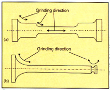 |
| Fig 3: Ceramics have different sensitivity to maching conditions. |
The importance of grinding parallel to the expected direction of stress can be seen in the test results recorded in Figure 3a. For this study, researchers prepared a standard specimen for the testing of tensile stress. When the specimen is tested, the maximum tensile stress is produced along the specimen’s axis. Therefore, the preferred grinding direction to reduce the influence of machining-induced damage during the test is along the specimen’s axis. If the specimen is machined transversely, which is the conventional method, machining damage on the surface may influence the point at which the specimen fails under tension. The test results, therefore, will be skewed by the machining process and not indicate the inherent property of the material to resist tensile stress.
A shop grinding ceramic automobile valves might consider the stresses the valve will experience in use in determining which direction to grind the part. Finite element analysis of valve stress has shown that the maximum tensile stress is near the valve seat during the combustion event as shown in Figure 3b. It is, therefore, preferable to machine the valve with grinding marks along the direction shown. The failure stress of the valves machined this way is about 30% higher than that of valves machined using the traditional transverse method.
Because the choice of machining procedure can have such a profound effect on the performance of the component, the machining procedure should be specified in the component’s design stage.
Design Better Ceramics
The cost-effectiveness of a grinding operation will also be influenced by the part designer’s choice of material. In many cases, it should be possible for the designer to use a ceramic with higher grindability to make the machining process more cost-effective. Based on the published data of ceramic properties, ceramics with similar or identical mechanical properties can vary in their grindability. This suggests that it is possible to find or develop ceramics that possess desirable mechanical properties that also rate high on grindability.
Recent work on dental ceramics has shown that the drilling rate of ceramics with higher wear resistance (a desirable property for such materials) can be higher than the drilling rate in ceramics with lower wear resistance. For example, researchers found that they could machine the harder FFC composite, which has a much lower wear coefficient, using a much higher mrr than could be used with an HCE composite with a higher wear coefficient.
Ceramic part designers cannot choose a ceramic or a machining process simply to satisfy geometrical requirements such as dimensional tolerances and surface roughness. They must also consider different ceramics’ susceptibility to machining-induced damage such as microcracking.
While it is not cost-effective to completely eliminate machining-induced damage, adapting the present machining technology to the application can minimize the influence of that this damage will have on the function of the machined ceramic components and achieve cost-effectiveness.
About the Author
Changsheng Guo is technical director and Ronald Chand is CEO of Chand Kare Technical Ceramics, Worcester, MA. This article is based on a paper Mr. Chand presented at the Ultrahard Materials Technical Conference, Windsor, Ontario, Canada, May 28-30, 1998.
Related Glossary Terms
- abrasive
abrasive
Substance used for grinding, honing, lapping, superfinishing and polishing. Examples include garnet, emery, corundum, silicon carbide, cubic boron nitride and diamond in various grit sizes.
- ceramics
ceramics
Cutting tool materials based on aluminum oxide and silicon nitride. Ceramic tools can withstand higher cutting speeds than cemented carbide tools when machining hardened steels, cast irons and high-temperature alloys.
- composites
composites
Materials composed of different elements, with one element normally embedded in another, held together by a compatible binder.
- coolant
coolant
Fluid that reduces temperature buildup at the tool/workpiece interface during machining. Normally takes the form of a liquid such as soluble or chemical mixtures (semisynthetic, synthetic) but can be pressurized air or other gas. Because of water’s ability to absorb great quantities of heat, it is widely used as a coolant and vehicle for various cutting compounds, with the water-to-compound ratio varying with the machining task. See cutting fluid; semisynthetic cutting fluid; soluble-oil cutting fluid; synthetic cutting fluid.
- creep-feed grinding
creep-feed grinding
Grinding operation in which the grinding wheel is slowly fed into the workpiece at sufficient depth of cut to accomplish in one pass what otherwise would require repeated passes. See grinding.
- depth of cut
depth of cut
Distance between the bottom of the cut and the uncut surface of the workpiece, measured in a direction at right angles to the machined surface of the workpiece.
- dressing
dressing
Removal of undesirable materials from “loaded” grinding wheels using a single- or multi-point diamond or other tool. The process also exposes unused, sharp abrasive points. See loading; truing.
- fracture toughness
fracture toughness
Critical value (KIC) of stress intensity. A material property.
- friability
friability
Characteristic of abrasive grains that describes their tendency to fracture or break apart when hit or placed under pressure. Highly friable abrasives cut more easily, but wear faster than other abrasives. Friable abrasives are usually used on soft, gummy materials or where heat produced by worn grits must be carefully controlled. Friability is usually related to the levels of impurities in the manufactured abrasive mineral.
- grinding
grinding
Machining operation in which material is removed from the workpiece by a powered abrasive wheel, stone, belt, paste, sheet, compound, slurry, etc. Takes various forms: surface grinding (creates flat and/or squared surfaces); cylindrical grinding (for external cylindrical and tapered shapes, fillets, undercuts, etc.); centerless grinding; chamfering; thread and form grinding; tool and cutter grinding; offhand grinding; lapping and polishing (grinding with extremely fine grits to create ultrasmooth surfaces); honing; and disc grinding.
- grinding wheel
grinding wheel
Wheel formed from abrasive material mixed in a suitable matrix. Takes a variety of shapes but falls into two basic categories: one that cuts on its periphery, as in reciprocating grinding, and one that cuts on its side or face, as in tool and cutter grinding.
- grit size
grit size
Specified size of the abrasive particles in grinding wheels and other abrasive tools. Determines metal-removal capability and quality of finish.
- hardness
hardness
Hardness is a measure of the resistance of a material to surface indentation or abrasion. There is no absolute scale for hardness. In order to express hardness quantitatively, each type of test has its own scale, which defines hardness. Indentation hardness obtained through static methods is measured by Brinell, Rockwell, Vickers and Knoop tests. Hardness without indentation is measured by a dynamic method, known as the Scleroscope test.
- machinability
machinability
The relative ease of machining metals and alloys.
- mechanical properties
mechanical properties
Properties of a material that reveal its elastic and inelastic behavior when force is applied, thereby indicating its suitability for mechanical applications; for example, modulus of elasticity, tensile strength, elongation, hardness and fatigue limit.
- parallel
parallel
Strip or block of precision-ground stock used to elevate a workpiece, while keeping it parallel to the worktable, to prevent cutter/table contact.
- phase transformation
phase transformation
Heat generated by machining action that causes changes in the workpiece’s surface layers. This can result in softer- or harder-than-desired workpiece surfaces, as well as undesirable changes in cutting tools.
- residual stress
residual stress
Stress present in a body that is free of external forces or thermal gradients.
- wear resistance
wear resistance
Ability of the tool to withstand stresses that cause it to wear during cutting; an attribute linked to alloy composition, base material, thermal conditions, type of tooling and operation and other variables.