
Tips for machining high-silicon aluminum.
Sometimes you need to "fight fire with fire," as the old saying goes. That certainly is the case when machining high-silicon aluminum.
This alloy has been used in production applications since the early 1980s, primarily by the automotive industry. Machining parts from it presents special problems due to its very abrasive nature.
Superabrasive cutting tools have made the use of high-silicon aluminum practical from an economic standpoint. Superabrasives can better resist the highly abrasive alloy’s tendency to shred tools made of conventional materials, and they hold up well despite the rigors of the machining process.
To understand the action taking place at the tool/workpiece interface, one needs to first understand the material and its special nature.
Material Composition
The chemical term for high-silicon aluminum is "hypereutectic." It is a nonferrous, metal-matrix composite with a primary silicon content of at least 11.8 percent. Silicon content can exceed 20 percent but rarely does.
"The exact point that the material becomes a hypereutectic aluminum depends on whatever else is added to the material mix during the casting process," explained the chief metallurgical engineer for the KUS/Zollner Piston Division, Gordon Vander Velde. "The addition of copper, magnesium, phosphorus or strontium all play a role in the levels at which the precipitation of primary silicon occurs."
The density and formation of the primary silicon pArticles improve the material’s mechanical properties. Compared to aluminum that has a silicon content less than 11.8 percent, hypereutectic aluminum is stiffer, has greater fatigue strength, is lighter, and has better wear resistance and thermal properties.
These characteristics are particularly attractive to the auto industry. Smaller, hotter-running engines are more durable when their components are manufactured from hypereutectic aluminum. One application is high-performance pistons used in gasoline engines, where thermal distortion in the bore is a common problem. The use of hypereutectic-aluminum pistons in high-performance and medium-duty diesel engines also has increased. And more transmission components, steering components and wheels are being produced from hypereutectic aluminum.
Besides automakers, the manufacturers of jet engine components, compressor parts and marine engines benefit from high-silicon aluminum.
Users of high-silicon aluminum understand the drawbacks of manufacturing products from the material. It costs roughly 5 to 10 percent more because of the addition of certain elemental additives, and both machining and foundry scrap rates are higher.
The ability to successfully cast the product is more difficult for two main reasons. One, the alloy generally requires a hotter pour temperature, because the mold must be filled before solidification due to the tendency of the primary silicon to clump up. And two, the temperature range in which the material converts from a liquid to a solid (the eutectic point) can be very narrow - as narrow as 1° or 2° F. The accuracy with which the temperature is controlled can determine the type of alloy that results.
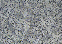
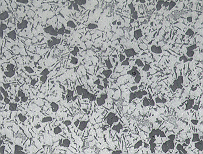
The micrograph at left shows the structure of a low-silicon aluminum that contains less than 11.8 percent silicon. At right is a hypereutectic aluminum containing 16 percent silicon (dark areas).
High-silicon aluminum poses similar challenges whether it’s milled, turned, drilled, reamed, tapped or ground.
However, foundry costs can pale in comparison to the higher cost of machining hypereutectic aluminum. The alloy poses similar challenges whether it’s turned, milled, drilled, reamed, tapped or ground.
High-Quality Tools Needed
Certain steps should be followed to economically machine hypereutectic aluminum. Perishable tools, permanent tooling, workholding, ways and slides, ballscrews and machine covers all suffer from the abrasive character of this material. As the silicon content rises in the material, so do the abrasiveness and the degree of machining difficulty. Hard pArticles of free silicon found in the matrix cause chips to be torn rather than sheared from the workpiece, which leads to extreme tool wear.
Abrasion, however, is the primary source of tool wear. As the cutting edge of the tool comes in contact with the larger silicon pArticles in the aluminum matrix, the pArticles chip away microscopic bits of the tool edge, whether it’s made of carbide or polycrystalline diamond. Edge deterioration leads to increasingly higher cutting forces at the tool/workpiece interface, causing gradual - and sometimes catastrophic - tool failure.
A HSS cutting tool has little value when machining high-silicon aluminum. It dulls within seconds of contacting the material. And carbide, even coated carbide, reacts as if it had come into contact with a grinding wheel. A carbide tool used in a high-volume production application becomes dull within minutes.
To date, diamond is the only cutting material that has exhibited an ability to machine high-silicon aluminum in a high-volume-production environment. A thin PCD film usually is applied to a carbide substrate that has been cut into the desired shape, or tip, by a wire-type electrical discharge machine. The procedure then requires the diamond tip to be brazed to the insert or tool body with a torch or via an induction brazing operation.
If surface finish is not a consideration, good starting points for turning are a 1,700-sfm cutting speed and a 0.015-ipr feed at a 0.060" DOC.
The micrograph at left shows the structure of a low-silicon aluminum that contains less than 11.8 percent silicon. At right is a hypereutectic aluminum containing 16 percent silicon (dark areas).
Fairly recent developments in coating technology have produced diamond-coated tooling. Diamond coatings are still fairly new, though, and have not overtaken PCD film as the material of choice.
High-quality tools are an absolute must when machining hypereutectic aluminum. Superior tools have a smooth radius and good surface finish on the front clearance face. Some lapping lines are permissible on the top face, but the edge must be free of chips when examined at 5005 magnification.
Most cutting edges are "up-sharp" or have a 0.001" edge hone. Any deviation at the edge caused by improper grinding, lapping or handling practices will promote erosion and lead to BUE, which will greatly reduce tool life. And, if pits appear in the clearance face, a poor cutting edge will result.
PCD is an extremely hard material, but tools made from it have a very fragile cutting edge. Mechanical forces and vibration cause small pArticles of the diamond to break away from the cutting edge, which accelerates edge deterioration.
When chatter occurs during machining operations that involve high-silicon aluminum and a PCD tool, the tool is usually suspected of being the source. However, machine integrity and/or toolholder rigidity is often the culprit. Both tool life and production output will increase by using high-quality spindles and axes drives, along with rigid toolholders.
The sound of chatter is a harbinger of imminent tool failure. The source of the problem needs to be addressed immediately if the diamond cutting edge is to meet its projected wear life.
PCD product quality and consistency can vary dramatically from manufacturer to manufacturer. The properties of various binders, catalyst levels and diamond-to-diamond bonding makes buying on price alone a risky proposition.
The adage about "getting what you pay for" may be old and overused, but when it comes to selecting PCD tools, it’s often true. The best way to ensure your tools are of a high quality is to get to know your supplier and, if possible, your supplier’s supplier. You should at least be aware that many manufacturers outsource the fabrication of their PCD tools to smaller specialty shops. This can sometimes lead to quality-assurance problems.
When quoting jobs that require the use of PCD tools, be sure to factor your tooling costs carefully. Remember that PCD tools not only cost more - sometimes 10 times more than their solid-carbide counterparts - but the lead times needed to produce them are often longer as well.
Additionally, because there are usually no "next best" substitutes for tools that can machine hypereutectic aluminum, you’ll want to consider keeping a healthy supply of PCD tools on hand at all times. Cost considerations that do not allow for on-the-shelf inventories may adversely affect production quotas. It might be wise to have a blanket-order policy in place for your PCD tools.
Machining Recommendations
In general, when machining aluminum that has a silicon content that exceeds 16 percent, use a PCD tool made from a coarse-size grain. Run the tool at a high feed rate and a lower spindle speed, especially when milling or performing other operations that involve interrupted cuts. For general-purpose applications, where the percentage of silicon content in the material is less than 16 percent, utilize a medium-size grain. And when a good surface finish is required, a fine-grain structure is desirable.
Flood coolant will aid in clearing chips and remove heat from the cutting edge and workpiece. But the use of a high-pressure coolant-delivery system offers considerable advantages, particularly when drilling.
The buildup of material on the tool’s cutting edge is a constant problem. This is due, in part, to the microscopic erosion that takes place during the cutting cycle. While this cannot be eliminated, it can be significantly reduced.
Following are some tips for specific operations.
Turning, Milling. Roughing cuts made in high-silicon aluminum with PCD tools should be done at the maximum practical feed rate and DOC.
When machining high-silicon aluminum, it’s important that the machine tool used be equipped with high-quality spindles and axes drives, and that the tools are mounted in rigid toolholders.
If surface finish is not a consideration, good starting points for turning are a 1,700-sfm cutting speed and a 0.015-ipr feed at a 0.060" DOC. For milling with a 4"-dia., 5-tooth, 45° lead-angle facemill, for example, start at 1,700 sfm (1,600 rpm), a 0.075-ipr feed, which calculates out as a 0.015-ipt chip load, and a 0.060" DOC.
The total DOC should not exceed 60 percent of the tool tip’s length, as measured from the nose back. Exceeding 60 percent of the length can cause catastrophic failure of the brazing that secures the tip to the carbide insert.
As the DOC is increased, the cutting speed should decrease. For example, the draft angles of a casting increase during the cut, so periodic speed adjustments need to be made. An alternative is to simply preset the surface-speed adjustment to the largest DOC. Be careful, though, if you try to use a constant surface footage to make a facing cut. Material that is removed along the draft angle of the casting will often build up as you approach the workpiece’s centerline.
Interrupted cuts, when either milling or turning, usually require a decrease in feed.
Finish settings depend upon the required radii and the specified microfinish. A good starting point for a 1/32-radius tool is 2,000 to 2,500 sfm, with a feed rate of 0.005 ipr. Personal experience has shown that the feed rate should not exceed one half the tool’s nose radius. For this reason, when determining your process requirements, use the largest radius possible that will not cause vibration. Rake and clearance angles on tools designed for high-silicon aluminum will normally be the same as for other forms of aluminum.
If surface finish is not a consideration, good starting points for turning are a 1,700-sfm cutting speed and a 0.015-ipr feed at a 0.060" DOC.
Drilling, Reaming, Tapping. Until a few years ago, the technology did not exist to economically drill or tap with a diamond tool. Today, PCD diamond-tipped drills, step drills, reamers and rotary form tools are available from several prominent suppliers. Tapping, however, still relies largely on carbide technology.
Drilling hypereutectic aluminum with a standard HSS twist drill is an exercise in futility. Sometimes, carbide drills used to produce shallow holes (0.250" and smaller) will provide adequate results. But a PCD-tipped drill should be employed whenever possible.
The abrasive nature of high-silicon aluminum is the chief nemesis of drill wear life. This is primarily the result of two factors: chip packing and dwell time inside the hole. Optimum flute and drill-point designs, in conjunction with proper coolant technique, are imperative to success. Flutes with high-helix angles are more effective at chip removal than standard drills with lower helix angles. When combined with a coolant-fed body, high-helix drills can handle most deep-drilling tasks.
The value of high-pressure coolant systems for hole work cannot be overemphasized. High-helix flutes and a high-pressure through-coolant tool can extend drill life dramatically. The extent of the improvement is application-specific.
To give you an idea of the production gains possible, I once used a standard 0.250"-dia., PCD-tipped drill to produce a 0.550"-deep hole in high-silicon aluminum. With flood coolant, I drilled 30,000 pieces. After switching to a high-helix, PCD-tipped drill with high-pressure coolant, the part count climbed to over 100,000 pieces.
Reaming high-silicon aluminum usually requires a 4- to 6-flute tool that has a chamfer with a 90° included angle. In many applications, a PCD-tipped reamer will not run any faster than its carbide counterpart. The main benefit of a PCD reamer is its longevity.
GE Superabrasives conducted a study in which a die-cast, hypereutectic aluminum steering component was reamed by a carbide step reamer and by a PCD-tipped step reamer. The tools were run at 234.8 sfm and a 0.010" feed; a soluble-oil cutting fluid was used.
Tool life for the PCD reamer was 48 times that of the carbide tool. The PCD reamer produced 9,600 pieces per regrind, compared to the 200 pieces per regrind for the carbide tool. Total cost per piece was $0.06 per piece for the PCD tool compared to $0.28 for the carbide tool. The initial cost of the PCD reamer was $1,250; the carbide tool cost $292.37.
Because of a PCD reamer’s significantly higher cost, it’s critical to handle the tool properly and ensure its easy entry into the drilled hole. Diamond tools are unforgiving when it comes to sudden shocks or excessive deflection.
Tapping high-silicon aluminum is difficult. Most manufacturers recommend the use of a carbide tap whose cobalt binder constitutes a fairly low percentage of the tool material. And, they say, a micrograin-tungsten-carbide grade provides a good balance of rupture strength and wear resistance.
Tapping high-silicon aluminum requires a cutting fluid with greater lubricity than is needed when tapping other materials. The typical fluid ratio of 20:1 should be changed so that the water-to-lubricant concentration is 4:1.
Grinding. Form grinding workpieces made of hypereutectic aluminum should be done with an electroplated diamond wheel. Producers of high-silicon-aluminum products recommend electroplated wheels over any type of ceramic bond.
In foundry snag-grinding operations involving high-silicon aluminum, where removing gates and risers may be required, suppliers of grinding products recommend a wheel with a 50-50 blend of 14-grit black SiC and Al2O3 in an R-grade, resinoid bond of normal structure. This wheel reportedly offers a good balance between metal-removal rate and wheel life.
When machining high-silicon aluminum, it’s important that the machine tool used be equipped with high-quality spindles and axes drives, and that the tools are mounted in rigid toolholders.
Meeting the Challenge
Machining hypereutectic aluminum can be challenging and, if done improperly, very expensive. PCD diamond tools can help you meet the challenge if you adhere to these basic tenets:
- Buy the best-quality tools you can find. Superior tools have a smooth radius and good surface finish on the front clearance face.
- Evaluate and improve your part-handling practices and fixture rigidity. PCD tools are fragile. Handle with extreme care. Both tool life and production output will increase by using high-quality machine spindles and axes drives, along with rigid toolholders.
- Use high feed rates and slower speeds to minimize tool wear.
- When quoting a job that requires the use of diamond tools, remember to factor your tooling costs carefully.
About the Author
Kim Pontius is operations manager at TD&M Production Machine, a New Haven, Ind., company that provides contract machining services and builds special equipment. He has over 20 years of combined machining, engineering and management experience.
Related Glossary Terms
- abrasive
abrasive
Substance used for grinding, honing, lapping, superfinishing and polishing. Examples include garnet, emery, corundum, silicon carbide, cubic boron nitride and diamond in various grit sizes.
- built-up edge ( BUE)
built-up edge ( BUE)
1. Permanently damaging a metal by heating to cause either incipient melting or intergranular oxidation. 2. In grinding, getting the workpiece hot enough to cause discoloration or to change the microstructure by tempering or hardening.
- chatter
chatter
Condition of vibration involving the machine, workpiece and cutting tool. Once this condition arises, it is often self-sustaining until the problem is corrected. Chatter can be identified when lines or grooves appear at regular intervals in the workpiece. These lines or grooves are caused by the teeth of the cutter as they vibrate in and out of the workpiece and their spacing depends on the frequency of vibration.
- clearance
clearance
Space provided behind a tool’s land or relief to prevent rubbing and subsequent premature deterioration of the tool. See land; relief.
- coolant
coolant
Fluid that reduces temperature buildup at the tool/workpiece interface during machining. Normally takes the form of a liquid such as soluble or chemical mixtures (semisynthetic, synthetic) but can be pressurized air or other gas. Because of water’s ability to absorb great quantities of heat, it is widely used as a coolant and vehicle for various cutting compounds, with the water-to-compound ratio varying with the machining task. See cutting fluid; semisynthetic cutting fluid; soluble-oil cutting fluid; synthetic cutting fluid.
- cutting fluid
cutting fluid
Liquid used to improve workpiece machinability, enhance tool life, flush out chips and machining debris, and cool the workpiece and tool. Three basic types are: straight oils; soluble oils, which emulsify in water; and synthetic fluids, which are water-based chemical solutions having no oil. See coolant; semisynthetic cutting fluid; soluble-oil cutting fluid; synthetic cutting fluid.
- cutting speed
cutting speed
Tangential velocity on the surface of the tool or workpiece at the cutting interface. The formula for cutting speed (sfm) is tool diameter 5 0.26 5 spindle speed (rpm). The formula for feed per tooth (fpt) is table feed (ipm)/number of flutes/spindle speed (rpm). The formula for spindle speed (rpm) is cutting speed (sfm) 5 3.82/tool diameter. The formula for table feed (ipm) is feed per tooth (ftp) 5 number of tool flutes 5 spindle speed (rpm).
- eutectic
eutectic
1. Isothermal reversible reaction in which a liquid solution is converted into two or more intimately mixed solids on cooling, the number of solids formed being the same as the number of components in the system. 2. Alloy having the composition indicated by the eutectic point on an equilibrium diagram. 3. Alloy structure of intermixed solid constituents formed by the eutectic reaction.
- facemill
facemill
Milling cutter for cutting flat surfaces.
- fatigue
fatigue
Phenomenon leading to fracture under repeated or fluctuating stresses having a maximum value less than the tensile strength of the material. Fatigue fractures are progressive, beginning as minute cracks that grow under the action of the fluctuating stress.
- fatigue strength
fatigue strength
Maximum stress that can be sustained for a specified number of cycles without failure, the stress being completely reversed within each cycle unless otherwise stated.
- feed
feed
Rate of change of position of the tool as a whole, relative to the workpiece while cutting.
- fixture
fixture
Device, often made in-house, that holds a specific workpiece. See jig; modular fixturing.
- flutes
flutes
Grooves and spaces in the body of a tool that permit chip removal from, and cutting-fluid application to, the point of cut.
- gang cutting ( milling)
gang cutting ( milling)
Machining with several cutters mounted on a single arbor, generally for simultaneous cutting.
- grinding
grinding
Machining operation in which material is removed from the workpiece by a powered abrasive wheel, stone, belt, paste, sheet, compound, slurry, etc. Takes various forms: surface grinding (creates flat and/or squared surfaces); cylindrical grinding (for external cylindrical and tapered shapes, fillets, undercuts, etc.); centerless grinding; chamfering; thread and form grinding; tool and cutter grinding; offhand grinding; lapping and polishing (grinding with extremely fine grits to create ultrasmooth surfaces); honing; and disc grinding.
- grinding wheel
grinding wheel
Wheel formed from abrasive material mixed in a suitable matrix. Takes a variety of shapes but falls into two basic categories: one that cuts on its periphery, as in reciprocating grinding, and one that cuts on its side or face, as in tool and cutter grinding.
- high-speed steels ( HSS)
high-speed steels ( HSS)
Available in two major types: tungsten high-speed steels (designated by letter T having tungsten as the principal alloying element) and molybdenum high-speed steels (designated by letter M having molybdenum as the principal alloying element). The type T high-speed steels containing cobalt have higher wear resistance and greater red (hot) hardness, withstanding cutting temperature up to 1,100º F (590º C). The type T steels are used to fabricate metalcutting tools (milling cutters, drills, reamers and taps), woodworking tools, various types of punches and dies, ball and roller bearings. The type M steels are used for cutting tools and various types of dies.
- included angle
included angle
Measurement of the total angle within the interior of a workpiece or the angle between any two intersecting lines or surfaces.
- lapping
lapping
Finishing operation in which a loose, fine-grain abrasive in a liquid medium abrades material. Extremely accurate process that corrects minor shape imperfections, refines surface finishes and produces a close fit between mating surfaces.
- lubricity
lubricity
Measure of the relative efficiency with which a cutting fluid or lubricant reduces friction between surfaces.
- mechanical properties
mechanical properties
Properties of a material that reveal its elastic and inelastic behavior when force is applied, thereby indicating its suitability for mechanical applications; for example, modulus of elasticity, tensile strength, elongation, hardness and fatigue limit.
- metal-removal rate
metal-removal rate
Rate at which metal is removed from an unfinished part, measured in cubic inches or cubic centimeters per minute.
- milling
milling
Machining operation in which metal or other material is removed by applying power to a rotating cutter. In vertical milling, the cutting tool is mounted vertically on the spindle. In horizontal milling, the cutting tool is mounted horizontally, either directly on the spindle or on an arbor. Horizontal milling is further broken down into conventional milling, where the cutter rotates opposite the direction of feed, or “up” into the workpiece; and climb milling, where the cutter rotates in the direction of feed, or “down” into the workpiece. Milling operations include plane or surface milling, endmilling, facemilling, angle milling, form milling and profiling.
- polycrystalline diamond ( PCD)
polycrystalline diamond ( PCD)
Cutting tool material consisting of natural or synthetic diamond crystals bonded together under high pressure at elevated temperatures. PCD is available as a tip brazed to a carbide insert carrier. Used for machining nonferrous alloys and nonmetallic materials at high cutting speeds.
- polycrystalline diamond ( PCD)2
polycrystalline diamond ( PCD)
Cutting tool material consisting of natural or synthetic diamond crystals bonded together under high pressure at elevated temperatures. PCD is available as a tip brazed to a carbide insert carrier. Used for machining nonferrous alloys and nonmetallic materials at high cutting speeds.
- rake
rake
Angle of inclination between the face of the cutting tool and the workpiece. If the face of the tool lies in a plane through the axis of the workpiece, the tool is said to have a neutral, or zero, rake. If the inclination of the tool face makes the cutting edge more acute than when the rake angle is zero, the rake is positive. If the inclination of the tool face makes the cutting edge less acute or more blunt than when the rake angle is zero, the rake is negative.
- reamer
reamer
Rotating cutting tool used to enlarge a drilled hole to size. Normally removes only a small amount of stock. The workpiece supports the multiple-edge cutting tool. Also for contouring an existing hole.
- soluble-oil cutting fluid
soluble-oil cutting fluid
Fluid in which oil is suspended in water. Because water is a superior heat-removal agent, this fluid is primarily used when lubrication is desirable but cooling is the key consideration. The ratio of oils and other additives to water varies with the application. For milling, the ratio of water to oil/additives runs 20:1 to 25:1. For sawing and other work, where a more confined tool/chip/workpiece condition is normal, a 10:1 ratio is used to improve lubricity. Additives include emulsifying agents that help keep the oil in suspension and substances that promote wetting, enhance lubricity, prevent chipwelding and inhibit rusting. Also known as emulsified oil. See cutting fluid.
- tap
tap
Cylindrical tool that cuts internal threads and has flutes to remove chips and carry tapping fluid to the point of cut. Normally used on a drill press or tapping machine but also may be operated manually. See tapping.
- tapping
tapping
Machining operation in which a tap, with teeth on its periphery, cuts internal threads in a predrilled hole having a smaller diameter than the tap diameter. Threads are formed by a combined rotary and axial-relative motion between tap and workpiece. See tap.
- toolholder
toolholder
Secures a cutting tool during a machining operation. Basic types include block, cartridge, chuck, collet, fixed, modular, quick-change and rotating.
- turning
turning
Workpiece is held in a chuck, mounted on a face plate or secured between centers and rotated while a cutting tool, normally a single-point tool, is fed into it along its periphery or across its end or face. Takes the form of straight turning (cutting along the periphery of the workpiece); taper turning (creating a taper); step turning (turning different-size diameters on the same work); chamfering (beveling an edge or shoulder); facing (cutting on an end); turning threads (usually external but can be internal); roughing (high-volume metal removal); and finishing (final light cuts). Performed on lathes, turning centers, chucking machines, automatic screw machines and similar machines.
- twist drill
twist drill
Most common type of drill, having two or more cutting edges, and having helical grooves adjacent thereto for the passage of chips and for admitting coolant to the cutting edges. Twist drills are used either for originating holes or for enlarging existing holes. Standard twist drills come in fractional sizes from 1¼16" to 11¼2", wire-gage sizes from 1 to 80, letter sizes A to Z and metric sizes.
- wear resistance
wear resistance
Ability of the tool to withstand stresses that cause it to wear during cutting; an attribute linked to alloy composition, base material, thermal conditions, type of tooling and operation and other variables.