Metal laser melting has made possible a number of groundbreaking developments in the medical field. One example is a 3D-printed bone drill that, unlike some traditionally manufactured drills, is designed not to damage tissue during surgery.
The Institute of Production Engineering and Machine Tools (IFW) at Leibniz University turned to a previous work partner, toolcraft GmbH, Georgensgmünd, Germany, while conducting an R&D project on the development of a tool able to cut bone without causing thermal-induced tissue damage.
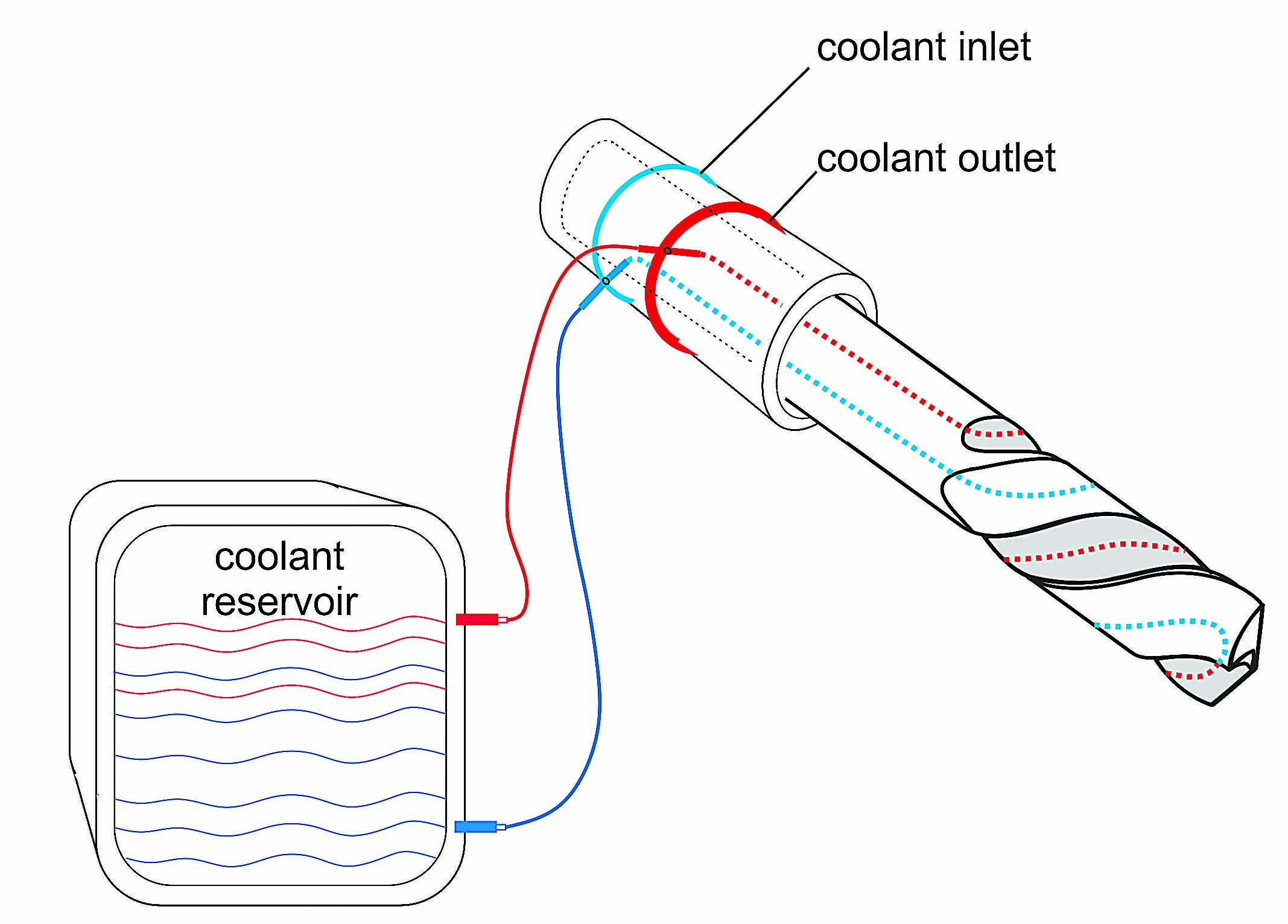
The cooling system inside the 3D-printed bone drill. Image courtesy of IFW.
This damage, called osteonecrosis, occurs at temperatures of 48° C (118° F) and higher. Because cooling the tool externally would likely cause fluid to enter the wound, it is not possible to apply conventional tools and cooling methods. To date, surgery has been performed iteratively—that is, the drilling process is repeatedly interrupted to keep the temperature as low as possible.
However, metal laser melting enables the manufacturing of drills with integrated cooling ducts. These ducts allow coolant to flow inside the tool—along the helix and back to the toolholder—without contacting the wound. Toolcraft, which manufactures tools, parts, assemblies, molds and injection-molded parts, also developed a nonrotating,
prespindle attachment with an inflow and outflow function for the coolant. As shown in the drawing on page 10, a continuous supply of coolant—water—is ensured by the attached coolant reservoir and pump.
The prototype was modeled on a conventional 6mm-dia. (0.236") bone drill. The shape of the drill had to be kept the same to make it easier for surgeons to adapt to the new tool. It was also important that the tool material be biocompatible, and, therefore, 1.4404 stainless steel was selected. Internal cooling ducts are 1.2mm (0.047") in diameter and remove heat from the cutting edge. Coolant enters and exits the drill via horizontally drilled holes. To attach the manifold—the sleeve housing the drill—there are grooves for circlips. The two chambers in the manifold are sealed.
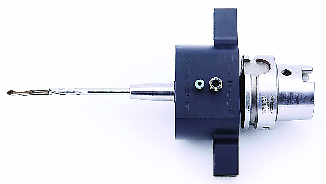
The internally cooled bone drill. Image courtesy of toolcraft.
At the outset of the project, the cooling capacity was determined in terms of the volumetric flow rate and temperature and thermal capacity of the coolant. A cutting speed of 2 m/min. (6.56 sfm) and a volumetric flow rate of 290 ml/min. (9.8 oz./min.) were recommended, with a feed rate from 0.07 to 0.35 mm/min. (0.002 to 0.0138 ipm).
The project team then developed a method for bringing a closed cooling circuit into the tool substrate while maintaining tool stability and ensuring that the tool was suitable for performing the required processes.
After the drill was 3D-printed by Concept Laser GmbH, Lichtenfels, Germany, it was ground to final size.
Using water as a coolant, IFW drilled and measured the process temperature in artificial and bovine bones. The researchers measured reference temperatures at higher and lower feed rates and when the tool cooling system was turned on and off. With the cooling system off, the temperature was more than 60° C (140° F). With cooling deployed, the temperature was less than 40° C (104° F).
Although a surgeon has yet to operate on a human patient with the drill, the test results show that the drill significantly reduces the temperature produced when drilling. Low feed rates are normally undesirable because they result in lengthier processes, more friction and higher temperatures. But these concerns are not critical with the 3D-printed tool because the internal cooling system compensates for increases in temperature—that is, low feed rates no longer lead to higher temperatures.
The technology could also be beneficial in a variety of other areas, such as saws. Toolcraft says it aims to commercialize the drill.
Contact Details
Related Glossary Terms
- coolant
coolant
Fluid that reduces temperature buildup at the tool/workpiece interface during machining. Normally takes the form of a liquid such as soluble or chemical mixtures (semisynthetic, synthetic) but can be pressurized air or other gas. Because of water’s ability to absorb great quantities of heat, it is widely used as a coolant and vehicle for various cutting compounds, with the water-to-compound ratio varying with the machining task. See cutting fluid; semisynthetic cutting fluid; soluble-oil cutting fluid; synthetic cutting fluid.
- cutting speed
cutting speed
Tangential velocity on the surface of the tool or workpiece at the cutting interface. The formula for cutting speed (sfm) is tool diameter 5 0.26 5 spindle speed (rpm). The formula for feed per tooth (fpt) is table feed (ipm)/number of flutes/spindle speed (rpm). The formula for spindle speed (rpm) is cutting speed (sfm) 5 3.82/tool diameter. The formula for table feed (ipm) is feed per tooth (ftp) 5 number of tool flutes 5 spindle speed (rpm).
- feed
feed
Rate of change of position of the tool as a whole, relative to the workpiece while cutting.