What Makes Diamond Coatings Work?
What Makes Diamond Coatings Work?
Researchers studying the performance of diamond coatings have found a number of factors of the coating process that determine the ultimate success of the coating. This article looks at factors such as substrate preparation, stresses in the coating and substrate and the diamond coating's formation patterns.
A report of a study that looks at the factors influencing a diamond coating's success.
An increasing number of cutting tool manufacturers and tool coaters are offering tools with diamond thin-film coatings applied using a chemical-vapor-deposition (CVD) process. The high hardness and refractoriness (thermal stability) of diamond make it a useful coating material for metalcutting. At the present time, most diamond coatings are applied to inserts, but with recently developed technology offering the potential to coat complex surfaces, it has become possible to use diamond thin-film coatings for metalcutting applications employing rotating tools such as drills, endmills, and taps.
The most important factor governing the success of a diamond coating in a commercial cutting tool application is the adhesion of the film to the substrate. Residual stresses are inherent in all CVD-diamond films, and these stresses directly govern the quality of the film/substrate bond. Consequently, these stresses have a significant effect on the cutting tool¹s performance. Other factors, such as film thickness, film roughness, substrate preparation, and substrate grain size, also affect film/substrate adhesion, and they must be considered along with the residual stresses whenever the quality of a diamond coating is evaluated.
A significant body of literature exists on the structure and properties of diamond and diamond films, but few studies have focused on the effects of interface stress on the performance of rotating tools and the mechanical properties of tungsten-carbide (WC)/diamond composites. Although the use of diamond films as coatings for tools is an established technology, there is insufficient published information on the fundamental nature of the entire raw-material-to-finished-product chain. Current thrusts seem to be aimed more at optimizing a few parameters for acceptable cutting tool life for a given material. These studies rarely consider the quality of the starting material, the surface-treatment and deposition processes, the deposited-film quality, or the stresses induced by the deposition process. This study examines these factors and tries to correlate them to a rotary tool¹s performance.
Cleaning and Coating
Commercially available carbide drills (94% WC, 6% cobalt) were used for this study. The drills measured 0.125" in diameter with 118° point angles and 25° helix angles. According to the manufacturer, the drills exhibited a lip-height variance of 0.001". A total of five drills were tested; four were coated and one remained uncoated. The drills that were to be coated were prepared using processes that have been established in previous studies as the most effective for cleaning the drills and removing surface cobalt. This preparation is necessary for proper diamond-film growth and adhesion. If the surface cobalt is not removed, the coating process will produce complex cobalt carbides rather than diamond on the surface of the tool. Because cobalt is the binder that holds the tool¹s WC grains together, the depth of this cobalt removal must be carefully controlled. If too much cobalt is depleted from under the surface, the tool¹s integrity will be jeopardized.
As a first step in the preparation process, all of the as-received drills that were to be coated were ultrasonically cleaned in reagent-grade acetone to remove surface organics. Following this, two different preparation methods were used to remove surface cobalt. In one method, designated the NA method, two drills were first ultrasonically cleaned with acetone. Then they were ultrasonically cleaned for 15 minutes in a solution of nitric acid and water mixed 1-to-1 by volume. Finally, they were rinsed and ultrasonically cleaned in ultra-pure water for five minutes. In the second procedure, designated the PT method, the remaining two drills were subjected to a proprietary chemical treatment for surface-cobalt removal. After their cobalt-removal treatments, all of the drills were ultrasonically cleaned again for five minutes in acetone and another five minutes in methanol. After they were cleaned, the drills were coated with a diamond film, which was deposited in the laboratory using a hot-filament CVD reactor. Through experimentation, the researchers found the coating parameters that promoted the best diamond growth.
Using a Dilor XY Raman spectrometer with a microscope attachment and CCD detector, the researchers analyzed the films to determine if true diamond was produced by the coating process. The spectrometer identifies a material by beaming laser light at a sample. For each type of material tested, the results show a spike in intensity at a unique wavelength. For this study, a wavelength of 1332cm-1, measured from a single-crystal diamond sample, was used as the baseline. A secondary use for Raman spectroscopy is to identify stresses in the examined material. These are indicated by Raman shifts, which occur when stresses in the test material cause the spike to move from the material¹s baseline wavelength. A shift in the positive direction indicates compression. A negative shift indicates tension.
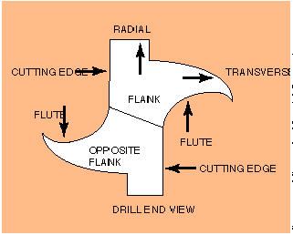
A more detailed analysis of the stresses in the film, the substrate, and the interface between the two was performed using X-ray deflection (XRD). The determination of stresses by XRD is based on classical elasticity theory. For this analysis, the films were step-scanned on WC and diamond with a chromium radiation of 2.2897 angstroms wavelength. The schematic for the stress-measurement points on the drill is shown in Figure 1. The drills were scanned for both WC and diamond diffracting planes. The residual stresses were automatically calculated from the scans.
Drilling tests were performed on a Magnum 800 horizontal machining center rated at 50 hp with a maximum spindle speed of 10,000 rpm. A cutting velocity of 300 sfm (9167 rpm) and a feed rate of 0.001" per cutting edge were used to drill blind holes 0.500" deep. The work material was a brake rotor composed of 40% aluminum oxide. Force and torque data were collected online via calibrated dynamometer and data-acquisition software.
Testing for Stress
Raman spectroscopy indicated that a diamond film was formed during the coating process and that the expected Raman shifts due to stress had occurred. The observed Raman shifts are tabulated in Table 1. The Raman peak position and shifts are given in centimeters-1. The shifts are related to the initial level of stress in the drills, the stress in the film, and the differences between these stresses for the two cobalt-removal treatments. The positive shift that was observed is explained by the presence of compressive stresses in the film and in the interface between the film and the substrate. These stresses are to be expected because diamond¹s coefficient of thermal expansion is lower than that of WC, and the compressive stresses that occur because of the mismatch dominate and overshadow the intrinsic growth stresses.
In the more detailed examination using XRD analysis, the researchers found that most of the stresses in the coated drills were compressive. In only one case was the stress found to be tensile. An examination of the stress levels in Figure 2 demonstrates stress imbalances between the radial and the transverse directions that are attributable to the drill-manufacturing process. It is likely that the drill-grinding process left unequal compressive stresses along these two directions.
Figure 2 also shows stress levels that are lower for the coated drills than for the uncoated ones. This may be due to the stress-relaxation effects of the high deposition temperatures. Variations in stress levels can be observed in orthogonal directions for each cutting edge. Also, the stresses are different for the diamond film and WC with the film showing higher stresses. This is presumably due to growth-related defects in the film and the higher expansion coefficient of WC propagating compressive stresses into the film. Thus, the compressive stresses increase from the substrate to the film and vary significantly for the samples tested.
Stresses in the rake face (flute) were also measured and the stress levels seen in the coated and uncoated drills were compared. These stress levels varied and were observed to be different from flank stresses. The post-CVD stresses ranged from slightly tensile to compressive.
The presence of tensile stresses in the diamond film may jeopardize a tool¹s performance by promoting film spalling at an earlier point in the tool¹s life. The nature of the drill geometry with inherent stress concentrations at the edges and the tip may result in variations in the stress levels. Although diamond has excellent refractoriness, the original stress variations and drill-edge deformities may lead to increased stress fluctuations at the interface during cutting with premature tool failure through film spalling.
A Closer Look
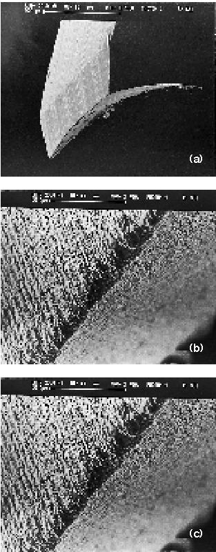
The researchers also examined the drills using a scanning electron microscope (SEM) before and after the coating process. Figures 3a and 3b show the cutting edge at two different magnifications. In both figures, imperfections and gouges can be seen along the edge. Figure 3c is an SEM image of the cutting edge of a drill after it was prepared with the proprietary treatment for cobalt removal. By comparing this image with the image of the cutting edge before treatment in 3b, we can see that the chemical surface treatment produces a porous surface and alters the nature of the flank and flute surfaces.
Figure 4a is an SEM image of one of the drills after it was coated with a diamond film. This drill was prepared for the coating process with the proprietary treatment. The image shows diamond coverage to be good overall, with the diamond growth conforming to the contours of the voids and deformities of the drill surface. The image also reveals a significant rounding of the cutting edge. The larger circular formations seen on the cutting edge, flank, and flute surfaces are clusters of individual diamond crystals growing out of the voids that existed on the substrate¹s surface.
Figure 4b is a magnified SEM image of the lumps of diamond seen in Figure 4a. Here, we can see that film growth is dense. A diamond cluster can be seen on the middle-left side of the SEM image. This cluster is growing out of a void near the cutting edge that can be seen in Figures 3a and 3b. Figure 4b also shows how rounded the cutting edge has become after it has been coated. It can be estimated from this SEM image that the rounding diameter is approximately 50µm at the widest point. Similar diamond growths and changes in cutting-edge geometry were observed on drills that were prepared using nitric acid.
Putting the Coating to the Test
The effects of the surface-preparation methods on the predeposition surface topography and the resultant film quality were expected to influence the effectiveness of the coated drills to machine metal. This was tested in drilling trials with the five drills.
In these tests, each of the four diamond-coated drills failed catastrophically after the first hole by fracturing at some point on the shank. In contrast, the uncoated drills lasted for about 15 holes.
Figures 5a and 5b show the force and torque plots, respectively, for the coated-drill operations. Figure 5c is a comparison force plot for the uncoated drill. It is evident that the diamond-coated drills experienced much larger forces along the z direction (thrust force along the longitudinal axis, Figure 5a) than the uncoated drills. Also, there is a distinct step-rise in drill force for the coated drills, and the initial magnitude of this force is similar to the force plot for the uncoated drills. The drills failed immediately after they experienced peak force and, consequently, experienced increased moments (Figure 5b). The initial force was due to the chipload, and the peak force was due to the plowing effect of the cutting edge. Because the geometries of both the coated and uncoated drills were identical, the differences in performance must have been due to changes brought about by the coating process. The edge-rounding effect of the diamond film may have caused the cutting edge to plow the work material rather than shear it, and this led to larger forces and catastrophic failure.
As Figure 4b shows, large diamond clusters tend to grow preferentially from voids along the cutting edge. During the drilling tests, these clusters were subjected to the entire chipload. This caused the tool to fail by creating severe stress concentrations and force and torque imbalances at discrete points along the cutting edge. The diamond-coated drills also exhibited unbalanced compressive interface stresses at the flute and rake surfaces. These stresses compounded those produced by the drilling process. The combination of stresses likely exceeded the breaking stress and moment limits of the drill. Additionally, the drills¹ original lip-height variance of 0.001" could have resulted in the absorption of the entire chipload at discrete points on the longer lip, and this could have led to premature drill failure.
The two different surface treatments yielded different levels of surface porosity and stress imbalances in the coated drills. However, it is unlikely that the drill failures were due to the surface treatments or stress imbalances, since both treatments produced drills that failed catastrophically.
It is possible that edge-rounding effects and the size variation in the diamond crystals were the key factors in determining the effectiveness of the diamond-coated drills. Smaller diameter drills have less rigidity stiffness than larger diameter ones. Proper sharpness of the cutting edge (which is related to edge rounding) and cutting-edge force balance (which is related to the entire force absorbed by the grain cluster) are instrumental to increased drill life. Therefore, it is essential to control the edge- rounding and cluster-formation phenomena during the generation of a diamond coating, and further research should be focused in these areas.
The results of this study help to define the effects of the CVD-diamond-coating process on rotating tools. The surface treatments did alter the drills¹ surfaces, and the application of the film produced uneven diamond growth and edge rounding. Further research is needed to correlate the effects of crystal clustering, cutting-edge imperfections, surface-preparation methods, and tool type and geometry on machining performance.
About the Authors
S. Chatterjee is a member of the technical staff at Bell Labs, Lucent Technologies, Holmdel, NJ. C.S. Feigerle is an associate professor and A.G. Edwards is a post-doctoral student at The University of Tennessee, Knoxville. This research was funded by the Center for Material Processing, The University of Tennessee, Knoxville, and the National Science Foundation. Additional support was provided by CARMET, Duncan, SC; sp3, Mountain View, CA; TEC, Knoxville, TN; and the Oak Ridge Centers for Manufacturing Technology. This article is based on a Society of Manufacturing Engineers (SME) technical paper and is used by permission of SME, copyright 1997, from the proceedings of the North American Manufacturing Research Conference XXV.
Figure 1: A schematic of the points on the drill at which stress measurements were taken.
Table 1: The positive Raman shifts that were
observed indicate the presence of compressive stress due to the different thermal-expansion
coefficients possessed by diamond and WC.
Figure 2: The radial and transverse stresses measured on an uncoated drill and on the
carbide substrate and coating of a CVD-
diamond-coated drill.
Figure 3: SEM images of the cutting edge of a drill as it was received (a), the same cutting edge at a higher magnification (b), and a cutting edge after it had been treated for cobalt removal (c).
Figure 4: SEM images of a CVD-
diamond-coated drill (a) and the coating under a higher magnification showing edge rounding and lumps of diamond growing out of voids in the substrate (b).