END USER: Van Riet Metaalbewerking BV, +31-497-591303, www.vanrietmetaalbewerking.nl.
CHALLENGE: Eliminate part deviations when performing lights-out machining.
SOLUTION: CAM software with the properly adjusted post-processor for automatically measuring parts on a machine tool.
SOLUTION PROVIDER: DP Technology Corp., (805) 388-6000, www.dptechnology.com.
When performing lights-out manufacturing, Ad van Riet, owner of Van Riet Metaalbewerking (Metalworks) BV, wants to know that mistakes aren’t being made in the dark. The eight-person company makes mechanical parts, including prototypes and production parts, typically from steel and nonferrous metals.
Based in Veldhoven, The Netherlands, Van Riet invested in a Mazak Variaxis 630-5X II 5-axis machine tool with an automated pallet system to increase part accuracy and reduce errors by decreasing manual operations. In addition to streamlining production processes, Van Riet cut labor costs and increased production by running the machine unattended for 18 to 20 hours a day.
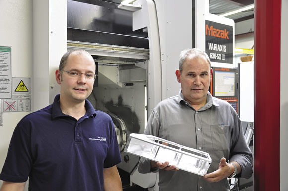
Foreman Bart van de Sande (left) and Owner Ad van Riet in front of Van Riet Metalworks’ Mazak Variaxis 630-5X II 5-axis machine tool.
To drive the machine tool, Van Riet purchased ESPRIT CAM software from DP Technology Corp., Camarillo, Calif. ESPRIT reseller Pimpel Benelux provides local support.
Embarking on its unattended machining mission, Van Riet created an automatic measurement cycle within the CAM package, reflected in the machine tool’s post-processor, so deviations from part dimensions can be automatically modified.
“When we arrive in the morning, we can be assured the parts are correct,” van Riet said. “So even when a tool wears, we don’t worry because any deviation is automatically corrected. The moment the sizes fall outside the tolerance, the controller automatically goes back to the starting line of the operation and the operation is done again.”
For example, if a measurement probe detects a hole is too narrow, which indicates extensive tool wear, the drill is automatically replaced. If a measurement is out of tolerance to the extent that correction is impossible, the operation is aborted.
In addition to the automatic QC processes, Foreman Bart van de Sande goes a step further by measuring completed parts at random. “With intense usage, tool inaccuracy increases, but with the on-machine measurement probe you don’t see any deviation in the measurement results,” he said.
When it comes to work offsets, embracing flexibility makes manufacturing more efficient, especially when machining multiple parts with varied offsets.
A work offset, or the orientation of the cutting tool—and therefore the workpiece—to the machine tool, is used to adjust the location of every tool loaded into the machine. On a milling machine, for instance, the offset changes the position of the spindle in the X and Y axes, and often the Z-axis, as well.
With support from Pimpel Benelux, Van Riet adjusted the machine tool’s post-processor to determine the work offset of the machine in three different ways.
Using one method, the “zero point,” or intersection of the X, Y and Z axes, is set in the middle of the table and all faces are recalculated from that point. A second method involves operating with the zero point in space, allowing ESPRIT to calculate from that point.
A third method entails using one of the 300 zero points Mazak has defined for the machine, combined with the zero points of the CAM software. By default, the post-processor for the Variaxis is written for 48 of these zero points, and Van Riet has allowed Pimpel to customize up to 300 zero points.
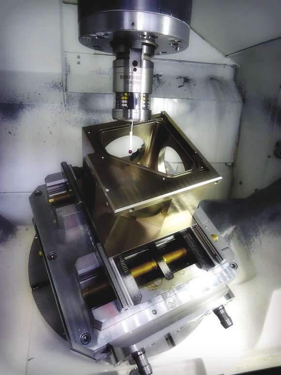
Automatic part measurement takes place on the Mazak 5-axis machine. Because of a special post-processor, Van Riet doesn’t need to measure repeatedly after machining a part.
With a solid model, programming in ESPRIT is much easier than programming at the machine tool, and reliable CAM simulation makes testing at the machine obsolete, according to van de Sande. “You get a good product faster and eliminate errors at the same time,” he said, adding that elimination of errors increases process security.
Programmers can program complex parts within a day. After a complex part is programmed, Van Riet needs just one part on the machine tool to fine-tune the program before machining parts unattended and within specification.
“The software is important to achieve continuous production,” van Riet said. “Thanks to our 5-axis machine and ESPRIT, machining these kinds of high-quality components is something we can do more efficiently.”
Related Glossary Terms
- computer-aided manufacturing ( CAM)
computer-aided manufacturing ( CAM)
Use of computers to control machining and manufacturing processes.
- gang cutting ( milling)
gang cutting ( milling)
Machining with several cutters mounted on a single arbor, generally for simultaneous cutting.
- milling
milling
Machining operation in which metal or other material is removed by applying power to a rotating cutter. In vertical milling, the cutting tool is mounted vertically on the spindle. In horizontal milling, the cutting tool is mounted horizontally, either directly on the spindle or on an arbor. Horizontal milling is further broken down into conventional milling, where the cutter rotates opposite the direction of feed, or “up” into the workpiece; and climb milling, where the cutter rotates in the direction of feed, or “down” into the workpiece. Milling operations include plane or surface milling, endmilling, facemilling, angle milling, form milling and profiling.
- milling machine ( mill)
milling machine ( mill)
Runs endmills and arbor-mounted milling cutters. Features include a head with a spindle that drives the cutters; a column, knee and table that provide motion in the three Cartesian axes; and a base that supports the components and houses the cutting-fluid pump and reservoir. The work is mounted on the table and fed into the rotating cutter or endmill to accomplish the milling steps; vertical milling machines also feed endmills into the work by means of a spindle-mounted quill. Models range from small manual machines to big bed-type and duplex mills. All take one of three basic forms: vertical, horizontal or convertible horizontal/vertical. Vertical machines may be knee-type (the table is mounted on a knee that can be elevated) or bed-type (the table is securely supported and only moves horizontally). In general, horizontal machines are bigger and more powerful, while vertical machines are lighter but more versatile and easier to set up and operate.
- solid model
solid model
3-D model created using “building blocks.” This is the most accurate way of representing real-world objects in CAD.
- tolerance
tolerance
Minimum and maximum amount a workpiece dimension is allowed to vary from a set standard and still be acceptable.
Author

Alan holds a bachelor’s degree in journalism from Southern Illinois University Carbondale. Including his 20 years at CTE, Alan has more than 30 years of trade journalism experience.