Understanding EDMed Surfaces
EDMed surfaces have their own texture and integrity considerations.
Quick take: EDMed surfaces need their own inspection and finishing assumptions because recast, texture, and subsurface effects can change downstream results. This page is most useful when it is read with material-behavior and finishing references.
Related references: Understanding Hardness in Metalworking, Tips for Sanding Titanium Parts Safely and Efficiently, and Machining Phenolic: Dust, Wear, and Tooling Guide.
Shops must know how to assess and improve EDMed surfaces before they apply this nontraditional machining process to new tasks.
As shops expand their use of electrical discharge m1achining (EDM), they face customers’ growing concerns about the surface changes EDM causes. Because EDM can alter the metallurgical properties of the workpiece material, it is important to understand the process’s potential effect on the durability of the workpiece. Methods for evaluating surface and subsurface damage and for removing part or all of the damaged material are essential to broaden the application of EDM.
Below the Surface
An EDMed surface is unlike that produced by any conventional machining process; it is characterized by a random lay of craters and globules of redeposited and recast material. The temperature of the plasma surrounding the spark is between 14,000° F and 24,000° F. This extreme temperature changes the metallurgy of the material. The region affected by these thermal changes is referred to as the heat-affected zone (HAZ). The HAZ is comprised of a recast layer of material that has been melted and resolidified at the surface, a layer that is harder than the original material, and an annealed layer.
The depth of each layer of the HAZ is directly proportional to the amount of current used in the EDM operation. The thickness of the recast and hardened layers is usually equal to the thickness of the annealed layer. In finishing operations, the depth of recast can be reduced to 0.00010″ or less, with total HAZ measuring between 0.00015″ and 0.00025″ deep. High-amperage roughing can easily produce redeposited and recast material up to 0.00400″ deep and total HAZ more than 0.00800″ deep.
Microcracking can occur in any of the layers of the HAZ, but it appears mainly in the recast layer. In finishing operations, microcracking may be 0.00010″ deep; in roughing operations, it may be up to 0.00150″ deep. In areas where short circuits have occurred, it is possible to find microcracks as deep as 0.10000″. In addition to microcracking, composite materials are susceptible to selective machining up to 0.00250″ deep because of varying melting points of the different constituents in the material. These materials also are susceptible to intergranular attack where the individual grain boundaries are compromised.
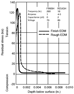
Figure 1: Residual-stress profiles for rough and finish EDM.
The thermally altered material is weaker than it was prior to EDMing. Although surface residual tensile stress is only 0.00100″ to 0.00200″ deep, it can adversely affect component strength. More importantly, residual stress can dramatically affect the high cycle fatigue strength of an EDMed component. This relates to the number of times the part can go through a thermal or mechanical stress cycle before it fails. High cycle fatigue strength may be reduced by up to 48% with low-current EDM and by 65% or more with high-current EDM if the surface is not post-treated (Figure 1).
Before considering post-treatment processes to remove the recast layer or the total HAZ, examine the EDMed surface to evaluate the damage. Various tools are available for evaluating surface roughness, flaws, and residual stresses.
Surface Examination
Visual observation is commonly used to assess an EDMed surface. It can be performed at varying levels of magnification using equipment as simple as a magnifying glass or as complex as scanning electron microscopy (SEM). Conventional microscopes and new video microscopes allow rapid visual inspection and provide a nondestructive means of identifying anomalies. Magnified visual inspection can’t always indicate whether or not a surface is acceptable, but it can signal the need for more in-depth analysis.
When detailed evaluation is required, the surface and subsurface can be examined by SEM at magnifications of 10,005 or more. Because a sample of the affected material must be sectioned and lapped to expose a cross-section of the HAZ, SEM is a destructive means of analysis. The image produced by SEM can quantify the presence of redeposited material, the depth of recast, the presence of microcracks, and the total depth of the HAZ. While SEM isn’t likely to be found in the average workshop, SEM services are available on a contract basis from a number of private and government-sponsored laboratories.
A simple surface assessment often suffices, but critical applications require random samples to be destructively analyzed to quantify damage and resultant strength reduction. These applications specify strict parameters that must be adhered to during EDMing to reduce the chance that the metallurgy will vary from piece to piece after EDMing.
Surface-roughness evaluation. There is typically a strong correlation between the surface roughness of an EDMed component and the depth of its thermally altered surface layer. Like strength and material integrity, surface roughness can be evaluated by several methods. This characteristic of the EDMed surface is most commonly expressed in Ra (roughness average) in microinches or micrometers. In Ra measurements, a mean line is constructed based on peak-to-valley distances. The surface-roughness value is stated as the arithmetic average of the absolute distances of all profile points from the mean line.
Instruments used to evaluate surface roughness generally fall into one of three categories: optical measurement, stylus measurement, or capacitance area measurement. In optical measurement, a light source of single or multiple wavelengths is directed at the workpiece surface, and relative measurements are made by analyzing the ratios of specular to scattered intensities. Although this method can provide a very good assessment of surface roughness, the cost of equipment may be prohibitive.
Stylus measurement is the most widely used method of surface-roughness evaluation. Stylus instruments are readily available and are less expensive than optical instruments. Surface roughness is measured by pushing or pulling a stylus, typically made of diamond, across the workpiece and recording the rise and fall of the stylus as it tracks the topography of the surface. The measured surface finish can be displayed as a numerical value, or it can be plotted as a topographical map of the surface. Tracing of the surface is normally done at low speeds to prevent the stylus from skipping from one peak to the next and giving erroneous surface-roughness readings. The diamond stylus also may scratch the surface of even the hardest materials, especially when repetitive readings are required.
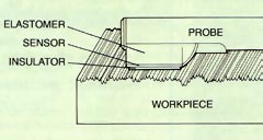
Figure 2: Capacitance method of surface-roughness evaluation.
Stylus measurements, which evaluate the surface roughness in one direction, may not give an accurate picture of an EDMed surface’s roughness, because unlike conventional machining processes, EDMing produces surface textures with no lay pattern. Capacitance area measurement was developed as an alternative method of measuring random lay finishes such as those on EDMed surfaces. To perform this kind of measurement, a very thin and compliant conductive sheet (sensor) is used as the first plate of a parallel-plate capacitance instrument, with the second plate being the workpiece (Figure 2). Capacitance area measurement is a total area assessment of the surface that is accomplished by measuring the void air volume between the two parallel plates. Different probe configurations are available to measure a variety of sizes and shapes.
Unlike stylus measurement, surface-roughness analysis by capacitance does not require the probe to be moved across the workpiece surface and, therefore, does not scratch the surface. Surface-finish readings can be expressed in Ra in either inch or metric units. The inexpensive probe is quite rugged and can be used directly on the shop floor. Because this type of equipment is more sensitive to oil and other debris that might interfere with the accuracy of data, the surface of the workpiece must be cleaned prior to measurement. A newly developed fringe-field capacitance probe performs a high-speed, noncontact scan of the workpiece surface. Using this probe, roughness evaluations can be performed directly on the CMM, where dimensional inspection occurs, and the full surface profile geometry can be determined.
Flaw detection. Sometimes the EDMed component requires analysis of the surface and subsurface at a micro level. In these cases, the main criteria might be the strength of the material and the presence of flaws without regard to surface finish or the depth of the HAZ. Flaws in the surface and subsurface can be identified by two methods—eddy current and ultrasound. In eddy-current analysis, an induced alternating current is passed through the workpiece, and the path of the electrical current is received by phase-sensitive sensors. The received signal is then analyzed to differentiate defects in the material from changes in physical shape or chemical composition.
Ultrasound evaluates a workpiece for the presence of flaws by using a transducer/receiver that outputs a multifrequency pulse of short duration to send sound waves through the part. The sound is then reflected back to the transducer/receiver, and this signal is examined for differences in the speed at which the signal is returned. Differences in the reflection speed not only indicate that a flaw exists within the workpiece, but also identify its location and severity. Both eddy-current and ultrasonic testing are nondestructive means of detecting the presence of workpiece defects both on the surface and in the subsurface.
Residual-stress analysis. When the EDMed component is to be exposed to high-temperature gradients or substantial mechanical loading, residual stress is the most important factor to be examined. Residual-stress analysis can be an excellent indication of the high cycle fatigue strength that can be expected from the component. An EDMed surface typically displays a very high degree of residual tensile stress in a very shallow layer of the workpiece surface. This stress makes the workpiece prone to mechanical failure.
A commonly used tool for assessing residual stress is X-ray diffraction, which measures the average stress in a volume of material defined by the area irradiated by the X-ray beam and the depth of penetration of the radiation. Although X-ray diffraction can be used in a nondestructive manner, it usually isn’t sufficient for a total analysis of an EDMed surface, because the depth of penetration of the X-ray beam is only 0.0002″ or less. For a complete evaluation, measurements must be performed at progressively deeper levels of the EDMed surface and subsurface. This is accomplished by lapping or etching away a few ten-thousandths of material at each level to examine the subsurface to a sufficient depth.
The information provided by the inspection of the EDMed surface, along with an understanding of the component’s application, will determine whether or not post-treatment of the EDMed workpiece will be required.
Post-Treatment
The process used to post-treat an EDMed component depends on specific requirements for cosmetics, mold release, or strength. The specification can be as little as requiring glass beading after EDMing or as prohibitive as requiring the removal of the entire HAZ. When only cosmetic improvements are needed, such as surfaces that will act as molding surfaces, smoothing the surface roughness normally suffices. Rather than removing layers of material to achieve the required surface roughness, post-treatment processes such as peening fill the gaps in the valleys of the profile with material from the peaks.
When the residual tensile stress on the surface and subsurface of the EDMed component must be relieved, it is necessary to use a post-treatment process that can remove the redeposited layer and the recast layer, as well as improve surface finish. By reducing the residual tensile stress, or by converting it to residual compressive stress by redistributing the material, the high cycle fatigue strength of the component is drastically improved. Components that are subjected to high loading conditions, such as compacting dies, are prone to premature failure that can be directly attributed to high residual tensile stress that reduces the strength of the material.
Components that are used in an environment where their failure would be catastrophic typically require removal of the entire HAZ as a safety precaution. Applications that fall into this category include aircraft, medical, and nuclear components. For rotating aircraft-turbine components, removal of up to 0.005″ per surface after EDMing is not unusual. The requirement for such stock removal limits the application of EDM. For example, wire EDM can produce fir-tree slots on turbine disks, but only at the development stage. Despite the speed and accuracy of the process, EDM is applied only to prototype components used in development testing of engines. Alternative means of machining the fir-tree slots, normally at a higher cost than wire EDM, are used for production engine sets.
Once it has been determined that some type of post-treatment of the EDMed surface must be performed, the primary consideration is the amount of material to be removed. The finishing process may degrade the accuracy of the component due to the varying amounts of material that are removed from the different surfaces. After even the best of finishing processes, the surface may vary by ±5% to 10% of the total material to be removed by the finishing process. For example, if 0.0020″ of material is to be removed, it can be assumed that the amount removed during finishing will vary from surface to surface by as much as ±0.0002″. A secondary consideration in choosing the post-processing method is the loss of very sharp edges, since they will be prone to radiusing during the finishing process.
Glass beading. If the goal of post-treatment of the EDMed surface is to remove the redeposited surface pArticles, this can be accomplished by glass beading. In glass beading, small spheres of glass propelled by compressed air are directed at the workpiece surface by a nozzle. The impact of the glass beads on the surface removes the redeposited material and begins to seal cracks in the recast material.
Wet blasting. In wet blasting, the abrasives are carried in a liquid solution that can include anti-rusting agents, wetting agents, and lubricants. Because wet blasting typically uses a smaller abrasive grain size than glass beading does, it can produce a better surface finish. Both methods not only remove material and improve surface finish, but also reduce the residual tensile stresses of the surface.
Shot peening. When the ultimate goal of surface treatment is to reduce or negate residual tensile stress, shot peening is often preferred. In this method, which is similar to sand blasting or glass beading, cast-steel spheres from 0.003″ to 0.250″ in diameter are propelled at high velocity at the workpiece surface. The impact of the steel shots produces small spherical depressions that cause plastic flow and radial stretching of the surface metal, and the edges of the depression may rise slightly above the original surface. When shot peening is complete, the layer of residual compressive stress usually extends up to 0.005″ to 0.020″ below the surface.
The use of shot peening after EDMing can greatly enhance the high cycle fatigue of the EDMed component and is sometimes required in aerospace and high-performance automotive applications. However, the process is difficult to control, and sharp internal corners, where residual tensile stresses are highest, are inaccessible with this method.
Vibratory finishing. An alternate method of post-treatment for small-to- medium size parts is vibratory finishing. The workpiece is placed in a bowl containing either abrasive or nonabrasive media that is agitated by an eccentrically rotating mechanism. Surface-roughness improvements occur as the media collides with or rubs against the workpiece surface. As an additional benefit, a small degree of residual compressive stress is induced by the process, thereby increasing the fatigue strength of the EDMed component. Limitations of vibratory finishing include difficulty in accessing small passages and internal corners and the inability to remove the entire HAZ or maintain sharp edges.
Chemical milling. To rapidly improve surface roughness, the EDMed surface can be post-treated with chemical or electrochemical processes, which can remove a portion of the HAZ or the entire HAZ. Chemical removal, also known as chem-milling, is accomplished by exposing the workpiece to a chemical bath for a limited period of time, with the duration of exposure dictating the amount of material removal. Chemical milling permits selected areas to be machined, so that surfaces requiring no post-treatment can be masked to inhibit material removal. Surface-finish improvements by chemical milling can be anywhere from 40µin. to 200µin. Ra after processing. Chem-milling does have limitations, however. The process cannot remove stock from certain materials, holes, vertical and near-vertical side walls, and deep slots or ribs. Furthermore, there is a risk that cracks may be etched even deeper.

Figure 3: Schematic of the ECM process.
Electrochemical machining. A variation of chemical removal is electrochemical machining (ECM). Material removal occurs as a conductive electrolyte is circulated through the gap between a positively charged workpiece and a negatively charged electrode, while direct current is applied at high amperage and low voltage to the electrolyte. Material is removed from the workpiece as electrons are removed by the current flow, causing the metallic bonds of the molecular structure of the surface to break (Figure 3). Since the material is removed by deplating and is dissolved at the molecular level, it is free of metallurgical damage. This extremely fast process can totally remove the HAZ if required and can significantly improve surface roughness. Unlike the shape of the electrode for EDM, the shape of the tool for ECM is not a mirror image of the machined form. However, when ECM is properly performed, there is no wear to the tool, which means that the tool may never need to be replaced.
Ultrasonic polishing. Ultrasonics can be employed in two different ways to improve the surface roughness of the EDMed surface. The hand-held version resembles a pneumatic hand tool and is comprised of a high-frequency oscillator with a tip that is similar to a grinding stone. Because the operator must manipulate the tool manually over all surfaces of the workpiece, nonuniform amounts of material may be removed.
Another ultrasonic means of surface-roughness improvement is a full-form polishing method. This process utilizes a tool that automatically conforms to the shape of the cavity to be polished. The process requires no reshaping of the tool, which is manufactured from a highly abradable material such as glass, porous ceramic, or one of several carbon derivatives. The tool is vibrated at a nominal frequency of 20,000 Hz while an abrasive slurry is applied to the gap between the tool and the workpiece. The abrasive pArticles in the gap are propelled from the tool tip to the surface of the workpiece, and they remove material by impact grinding. Since the tool becomes shaped to the mirror image of the cavity to be polished during the early stages of the polishing cycle, material removal is very uniform on all surfaces of the workpiece. Surface-finish improvements can be as much as 10-to-1, although improvements are typically closer to 5-to-1. Full-form ultrasonic polishing can completely remove a reasonably shallow HAZ, but total removal of a deep HAZ usually isn’t economically feasible. However, the process does impart residual compressive stresses to the workpiece, increasing the component’s high cycle fatigue strength.
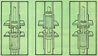
Figure 4: Schematic of the AFM process, which shows abrasive media being extruded through the workpiece and tooling.
Abrasive flow machining. Another free-abrasive means of improving surface roughness is abrasive flow machining (AFM), which also can be used to remove burrs and create radii. In AFM, two opposed cylinders extrude a semisolid abrasive media back and forth through passages formed by the workpiece and the tooling (Figure 4). The process is abrasive only in the extrusion area where the flow is restricted. The machining action is similar to a grinding or lapping operation as the abrasive media gently and uniformly hones the surface or edges. Materials from soft aluminum to tough nickel alloys, ceramics, and carbides can be successfully micromachined with this process.
The media is composed of a pliable semisolid carrier and a concentration of abrasive grains. The viscosity of the carrier and the abrasive grain size, type, and concentration can be varied to achieve specific finishing results. Higher-viscosity media is used for uniformly abrading the walls of large passages, while lower-viscosity media is generally appropriate for radiusing edges and for processing small passages.
The uniformity of the polished surface is one of the primary advantages of AFM, especially compared to manual finishing methods. This advantage leads to other benefits beyond lower labor costs, including improved part performance, longer tool life, less scrap and rework, and shorter inspection times.
Because AFM can remove the total HAZ regardless of its depth, the process embraces a wide range of applications, from critical aerospace and medical components to high production volumes of parts. AFM can reach even the most inaccessible areas and can process multiple holes, slots, or edges in one operation. Used to polish dies for extruding, drawing, forging, cold heading, and compacting, the process eliminates the expense and inconsistency of hand work. Uniform, controlled removal of material permits accurate sizing of die passages with minimal dimensional change. Typically, original EDMed finishes of 100µin. Ra are polished to below 10µin. Ra in a 10-min. cycle without special tooling requirements. Surface-finish improvements to one-tenth the original finish are generally expected from the process in such applications.
These post-treatment processes satisfy a variety of needs, from improving surface roughness to removing the entire HAZ. With a good understanding of the tools available to assess and improve EDMed surfaces, shops will find that almost any application can benefit from EDM.
About the Author
Lawrence Rhoades is president of Extrude Hone Corp., Irwin, PA.
Related Reading
- Related guide: Why Resources.


MFGAxis Discussion