Threads Will Roll
Threads Will Roll
Roll-forming taps produce internal threads by displacing the metal under pressure rather than cutting it. This article explains how to perform the operation to achieve good quality threads. Formulas and charts help the user calculate the proper size hole and the size of tap to use for a desired thread.
Roll-form taps are gaining popularity for producing high-quality internal threads quickly and cost-efficiently.
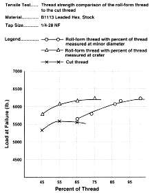
 Figure 1. Strength of roll-formed threads vs. cut threads. | |
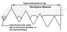
 Figure 2. Roll-form tap in workpiece. | |
Outdated perceptions have made many machining firms wary of roll-form tapping. While conventional cutting taps may be preferred for short production runs and very thin-sheet stock parts, roll-form tapping technology may provide a great many benefits for shops involved in long production runs and deep-hole tapping applications. For these applications, the potential benefits of using roll-form taps over cutting taps include longer tap life; lower cost per tapped hole; no chip production, which eliminates the cost and time needed for chip disposal; the ability to operate at increased speeds, which improves productivity; reduced tap breakage; and the production of threads with superior finish and strength (Figure 1).
In the past, these advantages over cutting taps may have been overshadowed by problems with the original roll-form tap design. Before improvements were made, extreme tapping torque was required, massive burrs were produced at the top of the hole, and excessively high heat was generated during roll-form tapping. Previously, it was difficult for the tooling on thread-grinding machines to generate the types of relief and configurations of lobes on the taps. Currently, roll-form taps with both plug and bottom tapered threads are produced on precision thread-grinding machines capable of accurately maintaining a controlled taper point, lead, thread form, pitch diameter, and relief (Figure 2). A controlled minor diameter on the tap can also be maintained so that the crater at the crest of the thread produced by the tap is barely noticeable. The controlled taper point grind, improved relief, and lubrication grooves have helped overcome the problems with the original design by lowering torque requirements, eliminating burrs, and reducing heat.
Today's roll-form taps achieve consistent tapping performance when proper consideration is given to preparing the hole, selecting the tapping fluid, evaluating the tapping equipment, and choosing the correct tap design.
Hole Preparation
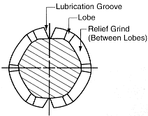
 Figure 3. Lobes and relief on roll-form tap. | |
For roll-form tapping, the hole diameter must be larger than it would be for a cutting tap. That's because the material being tapped is not cut but displaced. As the tap enters the hole, the material is pushed by the taper threads at the point of the tap and the lobes on the crests of the tap threads (Figure 3). The lobes are smaller in diameter at the front taper portion of the tap and gradually increase in diameter until they are the diameter of the thread to be produced. The material flows down the flanks of the tap threads, creating the actual 60° included angle for the thread.
There are drill charts available in wire gage, machine screw, fractional inch, and metric sizes for most roll-form taps. Because a larger-diameter drill is used for hole preparation, it is stiffer and less likely to bend and break. Other advantages of using a larger drill size include improved drill life, straighter holes, and higher feed rates to break up chips more effectively.
Because a roll-form tap displaces material, some material will be forced ahead of the tap and back toward the mouth of the hole, creating a small burr. For this reason, it is best to allow enough room in the bottom of the hole and to countersink or chamfer the hole prior to tapping so that the extruded material will be contained within the countersink and will not interfere with the mating part.
Cored holes in die-cast aluminum and zinc may be tapped easily with a roll-form tap, provided the core pins are changed to make the proper hole size in the part. Because core pins have a draft or are slightly tapered, the theoretical hole size should be at a point on the pin that is one-half the required length of engagement of the thread to be formed. The length of engagement is the axial distance over which two mating threads are designed to contact. In designing core pins for use with a roll-form tap, a chamfer should be included on the pin to accept the displacement of material that has been extruded by the tap at the mouth of the hole.
It is important to maintain close control of the hole size prior to tapping, especially when tapping very fine-pitch threads, because the hole size controls the final percentage of thread. For general applications having lengths of engagement of 1.5 diameters, 65% to 75% thread should be adequate for both product acceptance and thread strength. Roll-form tapping is not recommended for more than 75% thread, because there is not enough room for the material to flow, and the torque required will cause the tap to break.
The following formula is used to calculate the theoretical size of a drilled or cored hole before tapping:
| tap OD – | 0.0068 x % of thread threads per inch (tpi) | = hole size |
For example, the proper hole size to roll-form 65% of thread with a 1/4-20 NC roll-form tap can be determined as follows:
| 0.2500 – | 0.0068 x 65 20 | = 0.2280" |
The hole size is "theoretical" because adjustments are often needed. The material may not exhibit the same ductility from one heat lot to the next, and the larger pitch diameter used on roll-form taps may cause the material to flow more, leaving a smaller minor diameter after tapping.
Actual determination of the percentage of thread that has been tapped can be found by checking the minor diameter of the tapped hole with a cylindrical pin gage. The pin should be sized for the hole so that it enters the hole with light pressure. The following formula is used to calculate the actual thread percentage after tapping:
| tpi x (tap OD - pin dia.) 0.01299 | = % of thread |
For example, the percentage of thread after tapping with a 1/4-20 NC roll-form tap, where the tapped hole would accept a 0.2078"-dia. pin, is determined as follows:
| 20 x (0.2500 - 0.2078) 0.01299 | = 65% of thread |
To determine acceptance of the finished size, refer to the appropriate recognized thread specification standard (Table 1).
|
When calculating the wall thickness in the part where roll-form tapped threads are to be produced, a basic rule of thumb is to allow for no less than three times the single thread height (hb). The following formula is used to calculate hb for unified national threads:
| 0.649519 tpi | = hb |
hb x 3 = wall thickness in part
For example, the approximate wall thickness the part should have when using a 1/4-20 NC roll-form tap is determined as follows:
| 0.649519 20 | = 0.0325" |
0.0325 x 3 = 0.0975"
Tapping Fluid
Lubrication grooves ground into a roll-form tap along its length function as paths for the tapping fluid to reach the taper threads, where the forming action occurs. It is best to use a heavy-duty drawing fluid recommended by the metalworking lubricant company for applications involving cold extrusion or metal drawing processes. This type of fluid contains extreme-pressure additives, such as sulfur, chlorine, and some nonchlorine additives. The choice of tapping fluid depends on the amount of pressure required of the tap to form the thread.
The most critical feature of the tapping fluid is the lubricity between the tap and the wall of the hole being tapped. Even though the amount of heat produced between the tap and the wall of the hole is considerable as a result of the material being stressed beyond its elastic limit, it is more important to reduce the friction in this area with a drawing fluid, rather than with a fluid that is primarily a coolant. The heat is carried away in the fluid rather than going into the tap or the workpiece, and the additives in the drawing fluid react chemically with the workpiece material to form compounds to inhibit welding or galling. If no fluid is used, the tap will actually weld itself inside the hole or produce threads of poor quality.
Cleanliness of the drawing fluid is important since a chip from any operation prior to roll-form tapping would cause premature tap failure or other poor performance problems if the chip became wedged between the tap and the wall of the hole. A suitable filtration system and maintenance program for all processes prior to roll-forming is recommended to make sure the chips don't become a problem.
Tapping Equipment
For most tapping operations, conventional tapholders may be used, and the single-spindle equipment used on tapping heads, automatic screw machines, CNC machines, and lead-screw machines will be suitable. In multispindle applications, the required tapping torque must be carefully evaluated (Table 2).
|
The torque required varies with the yield strength." title="In tensile testing, the ratio of maximum load to original cross-sectional area. Also called ultimate strength. Compare with yield strength." aria-label="Glossary: tensile strength">tensile strength, yield strength, hardness, and chemistry of the material being tapped. The choice of either plug or bottom roll-form taper also affects the tapping torque, since less torque is required to distribute the forming action over a longer distance. The efficiency of the tapping fluid and the depth of the tapped hole are other variables that influence tapping torque. The additional torque required can range from none to more than three times that required for cutting taps.
It is important for the tapping machine to have adequate horsepower to achieve higher and more efficient tapping speeds. For most materials, the spindle speeds may be increased to drilling speeds. By overcoming the resistance of the material beyond its yield point, roll-form taps perform better at higher tapping speeds. Most ductile materials exhibit a natural characteristic to "spring back." When the tapping speed is high enough for the tap to get in and out of the hole before this elastic recovery takes place, the tapping process is improved. However, roll-form taps may also run at lower speeds with satisfactory results.
The following formula is used to determine the approximate machine horsepower requirements:
| tapping torque (in.-lb.) x spindle rpm 63,025 | = hp |
For example, the approximate machine horsepower to roll-form 75% of thread in 2024 T-4 aluminum with a 1/4-20 NC roll-form tap (bottoming style) at 850 rpm and 0.050 ipr is determined as follows:
| 80 (from Table 2) x 850 63,025 | = 1.08 hp |
Additional horsepower must be allowed for actuation of the machining unit. The machine tool builder can provide information about requirements for a specific application.
When using roll-form taps, it is recommended that tapping studies be conducted to determine the best hole size, the tapping speed, the efficiency of the tapping fluids, and the actual ductile behavior of the material being tapped before deciding optimum results. Materials with a minimum elongation of 8% and a maximum hardness of RC 30 are best-suited for roll-form tapping. Roll-form taps made from hardened HSS are able to produce quality threads in brass and low-carbon steel, as well as in difficult-to-machine materials like titanium and stainless metals. Roll-form tapping is also suitable for applications that require safety-critical threads (Table 1).
Tap Design
Some features of roll-form taps are often overlooked. For example, roll-form taps do not have cutting edges, which become dull and break down or cause chips to pack between the tap and the wall of the hole. The lobes are very narrow and are ground in between the relieved area of the tap. The lube grooves on a roll-form tap are not as deep as the flutes on a cutting tap, giving it a more rugged cross section. The enhanced strength of the roll-form tap design is very beneficial for smaller machine-screw-size taps in deep-hole tapping applications.
The pitch diameter can be held closer to the hi-gage (no-go limit), which improves the wear life of the tap. Because the material is formed very close to the size of the tap, oversize holes are not as common as when a cutting tap is used. There are also fewer problems with undersize holes, because roll-form taps do not shave the threads during tap reversal like cutting taps tend to do. In addition, the continuous thread of the tap assures accurate lead and tapped-hole gaging.
Bottom-Line Benefits
Roll-form taps produce consistent tapped holes and maintain this consistency for higher numbers of holes than cutting taps can achieve. The faster tapping speeds used with roll-form taps reduce cycle times on automatic tappers and screw machines, so more tapped parts per hour are being made.
Because roll-form tap life is much longer than that of cutting taps, fewer tap changes are required. There are actual cases of companies tapping the same number of holes with one roll-form tap as they did with 40 cutting taps. In one case, when roll-forming 65% of thread in die-cast aluminum, using a 5/16-18 NC roll-form tap with lubrication grooves and steam-oxide treatment, 7,000 through-holes were tapped with only one roll-form tap at 2,400 rpm on a vertical CNC tapping machine.
With roll-form taps, the actual cost per tapped hole can be minimized due to the substantial reduction in downtime caused by broken taps, entangled chips, and frequent tap replacement to maintain the quality of threads being tapped. For example, tapping 80,000 holes with a 1/4-20 NC roll-form tap costs $0.00016 per hole.
About the Author
Dan Gajdosik is senior engineer at Besly Products Corp., South Beloit, IL.


