Thread Rolling on CNC?
yield point, which ca…" title="Chipless, cold-forming material-displacement process where a rolling head is pressed into the workpiece to create threads. The material is stressed beyond its yield point, which ca…" aria-label="Glossary: thread rolling">Thread Rolling on CNC?
Thread rolling produces OD threads by cold profiling the thread form onto the workpiece rather than cutting. According to this article, this yields significant benefits over using single-point tools to cut threads. The article also discusses the different types of thread-rolling units and their uses on modern machine tools.
While thread-rolling technology has been used on screw machines and engine lathes for decades, rolling threads on machines that aren't dedicated to a single part is a relatively new and unfamiliar concept. Although the machining benefits of CNC may not directly pertain to yield point, which ca…" title="Chipless, cold-forming material-displacement process where a rolling head is pressed into the workpiece to create threads. The material is stressed beyond its yield point, which ca…" aria-label="Glossary: thread rolling">thread rolling, this process can optimize threading on CNC machines.
Today's CNC machines are very versatile and can be changed over quickly to help meet demands for just-in-time (JIT) manufacturing. But versatility is no longer the biggest benefit of CNC — more important is CNC's ability to produce higher-quality parts more quickly and efficiently. Tool changes are faster, and adjustments can be made without stopping the machine.
Like CNC, single-point threading is also very versatile. A single tool may be used to produce many different threads. This can be a very economical method of producing smaller quantities of parts. When parts are produced in greater quantities, however, single-point threading's versatility is less beneficial. To maximize effective tool life, single-point inserts are processed with a limited depth of cut, so multiple passes are needed to cut to the thread's full depth. The time needed to take these multiple passes can create a bottleneck. Additional passes may also be taken to deburr the thread, requiring additional machine tool time or a second operation outside the machine. Although CNC is bringing down total threading cycle times by making noncutting functions more efficient, these time savings are negated by the added time it takes to single-point thread. Thread rolling produces threads in one pass, reducing expensive CNC machining time.
In addition, when a thread must be rolled, the use of a thread-rolling head/attachment on CNC equipment can complete the workpiece in one operation, thereby eliminating a second operation on a separate thread-rolling machine.
A Stronger Thread
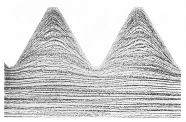 | Figure 1. Micrograph of a rolled V-type thread |
In addition to doing more work on one machine in less time, thread rolling has many technical advantages over single point threading. Instead of cutting or shearing the material, thread rolling cold-forms the profile to be produced. A hardened die made from tool steel or HSS displaces the material along the contours of the thread profile, plastically deforming the material into the final form. The workpiece material is stressed beyond its yield point, which causes it to flow and conform to the mirror image of the die's profile (Figure 1). The grain lines of the rolled material aren't interrupted like those of cut material; they are compressed and moved more perpendicular to the centerline of the part, increasing the thread's tensile strength 10% to 30% over cut threads (Figure 2). This aids in resisting the tensile forces acting against a thread, which pull along the centerline of the part. Parts that can benefit from this increase in tensile strength include cylinders, piston rods, and tie rods.
The compression of the material during the rolling operation causes workhardening at the thread's surface (Figure 3). This is most apparent in the thread's root and along its flanks, making them more wear-resistant. The compression of material to the die's form provides a very exact profile with a surface finish better than grinding can achieve. Shearing the material produces a rough surface finish, but compressing it produces a smoother and harder surface finish, resulting in greater resistance to wear, corrosion, and galling. This improved resistance is a particular benefit for valve stems and other parts that are susceptible to harsh, corrosive atmospheres. Nuts that must travel freely over long distances in contaminated atmospheres also benefit from the smooth surface finish.
A rolled thread also has up to 70% increased fatigue resistance over a cut thread. Since rolling is a chipless operation, the profile is free from burrs, tear marks, chatter marks, and sharp exit points, all of which are focal points for stress. The smooth, burnished surface of a rolled thread has fewer hills or valleys where stress can build up and cause the part to fail from fatigue. This characteristic is most beneficial at the thread runout, or distance of unusable or incomplete thread. If a part were to fail from fatigue, it would fail here at the end of the thread, where all the load is focused. Parts that are under a constant load greatly benefit from thread rolling because the threads have a smooth, workhardened, radiused, and burnished runout.
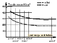 Figure 2. Fatigue test for cut and rolled threads | |
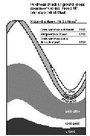 Figure 3. Hardness of a rolled thread compared with the component core. | |
With thread rolling, thread quality is more consistent from part to part than with single-point threading. Even with the best grind possible, a single-point threading insert will start to wear the moment it touches metal. The longer the thread to be cut, the greater the potential for deflection and chatter, resulting in shorter tool life. However, the dimensions of thread-rolling dies do not change with use. Every time the dies roll, they gain stress. The stress builds up to a point where the hardened material of the die just fatigues and breaks away in small pieces at the crest where the die is doing the most work. Up to this point, the dies will make the same profile every time. Practically no adjustments are needed throughout the life of the rolls, which is typically tens of thousands of parts per set.
Material Savings
Since thread rolling displaces material rather than removing it, smaller stock can be used to produce a given thread diameter than must be used with single-point threading. Whereas single-point threading is a reductive process, thread rolling actually increases the part's diameter to the thread's outer diameter. Therefore, the diameter of the part upon which the thread is to be rolled will be less than the outer diameter by an amount approximately equal to the depth of one thread. To single-point thread the same diameter, the machinist would have to start with stock of that diameter. For example, if a 1/4"-dia. thread were to be produced, 0.250"-dia. stock would be required to single-point thread. Thread rolling would require a stock diameter of approximately 0.214". That's a 25% savings in material.
In addition, thread rolling may negate many of the chip problems associated with materials such as 304 and 17-4 stainless steel, Inconel, and titanium.
Thread Forms
Thread rolling is applicable to many standard and special thread forms. Besides common 60° profiles, other types of threads that can be rolled include parallel- and taper-pipe, V-type, acme, knuckle, buttress, straight wood screw, and serrations (Figure 5). As long as the flank angles on each side of the thread add up to at least 20°, practically any special shaped thread can be rolled between 0.055" and 9.000" in diameter with a thread-rolling head/attachment. Just by changing rolls, a thread-rolling head/attachment also can knurl and burnish. In addition, depending on the specific application, it may be possible to reduce tube diameters, swage the ends of tubes, roll annular ring profiles (i.e. barbs and grooves), and mark logos, letters, and numbers.
Workpiece Material
Within given physical parameters, practically any workpiece material can be thread-rolled, including structural steels, casehardened steels, stainless steels, heat-treatable steels, aluminum, and nickel-base alloys such as Inconel 718. The three main physical parameters that determine whether rolling is feasible are elongation factor, hardness, and tensile strength. Because the material will be plastically deformed by pressure, it should have a minimum elongation factor of 5% to 7%. Cast iron, pure bronze, hard brass alloys, and other hardened materials that have less than 5% elongation are too brittle to be thread-rolled. As a general rule, material hardness should not exceed RC 40, and material tensile strength should not exceed 210,000 psi.
Chemical composition also can be a factor. The workpiece material should not contain more than 1% lead or additives for free machining. In addition, the type of profile and the amount of displacement have a direct impact on the material's ability to be rolled.
The workpiece material to be rolled may affect the choice of thread-rolling head/attachment, surface treatment on the thread roll, and thread-rolling system. There are three main systems: axial, tangential, and radial.
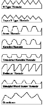 | Figure 5. Types of profiles that can be rolled. |
Axial
The axial system comes from the front (outboard) end of the part along the centerline (Figure 6). While thread lengths produced by the other two systems are limited to the width of the rolls, the axial system is designed to produce unlimited thread lengths. The thread form on the axial rolls consists of straight annular rings that are ground to the pitch of the thread to be produced. The rolls are positioned in the head at a skew angle that is approximate to the thread's helical angle, producing a forward motion; hence, the heads are self-feeding.
If the first ring on the axial roll were full profile, it would do all the work. Therefore, similar to a chamfer on a tap, a progression or lead is required to help the rolls start and to provide better tool life. By having more progressive rings on the rolls, tool life can be optimized on longer profile lengths.
A shorter progression can be used to allow threading up closer to a shoulder, but the rolls won't last as long. The closest that the axial system can thread to a shoulder is approximately 1 1/2 times pitch. Where it is desirable to thread very close to the shoulder, a tangential or radial thread-rolling system will do a better job.
Although the axial system can't thread as close to a shoulder as the other two systems, it can thread larger diameter stock. Since the axial rolls only produce one thread at a time, the heads are simpler in design. This leads to greater diameter capacity. Currently, the axial system can roll profiles up to 9" in diameter. Because the tangential and radial systems use the full width of the roll, their attachments tend to be bigger and more rigid for a given diameter capacity, so they would be too bulky to fit on a machine to roll profiles this large.
Tangential
The tangential system uses one roll above and one below the workpiece. The rolls are fed from the side (x-axis), pressing deeper with each revolution of the workpiece. When the centerline of the rolls is in line with the centerline of the workpiece, usually after 15 to 30 revolutions, the forming process is completed (Figure 7). Neither the part nor the rolls move axially. Therefore, the length of the thread that is formed depends on the width of the roll.
|
|
|
| Figure 6. Axial system. | Figure 7. Tangential system. |
As opposed to the axial system, which uses rolls with straight annular rings tilted at an angle, tangential attachments use helical profiled rolls that are mounted on straight stationary spindles. The thread helix angle to be produced is ground onto the roll; in other words, it is a mirror image of the thread. Therefore, it is just a matter of using left-hand rolls to produce a left-hand profile and right-hand rolls to produce a right-hand profile. However, the same attachment can be used with either type of roll.
If the face of the profile were 90° from the centerline of the roll, it would be a very weak point. Hence, the rolls are chamfered at both ends of the profile to provide a base of support for better roll life. The length of the chamfer is equal to the thread runout, or distance of unusable or incomplete thread to a shoulder, which is approximately 1/2 to 1 times pitch. Therefore, it's possible to thread very close to a shoulder.
Typical rolling times using a tangential system are two to three seconds. The radial system, meanwhile, achieves cycle times of typically less than one second.
Radial
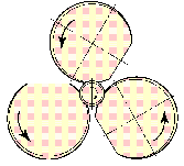
In the radial system, the rolls are geared together and spring-loaded. When the rolls are brought over the area to be threaded, the spring tension is released, causing the rolls to rotate. As on tangential rolls, the helix angle of the thread is ground onto the radial rolls, so left-hand rolls will produce a left-hand profile and right-hand rolls will produce a right-hand profile. In addition, radial rolls have flats for clearance to allow the workpiece to be inserted and removed from the thread-rolling head (Figure 8).
The first portion of the roll to contact the workpiece is ground inward eccentrically, so the distance from the center of the roll to a point on the inner wall of the roll is not the same from point to point (Figure 9). This eccentricity causes the thread rolls to press deeper into the workpiece as they rotate. The rolls complete the thread when they have rotated one revolution, bringing them back to the flats and automatically resetting the head.
|
|
|
| Figure 8. Radial system. | Figure 9. The profile on the radial rolls is ground inward eccentrically. |
The closest that the radial system can thread to a shoulder is 1/2 times pitch, which is closer than a single-point insert with a 60° cutting tip usually can thread. The radial system is mainly applicable to threads up to approximately 1 1/2" long. It produces threads more quickly than the axial and tangential systems do, and the rolls are designed to eliminate deflection problems that may result when the thread is run outboard using the tangential system.
The radial system also provides optimum results when the workpiece material's hardness and tensile strength make it less feasible to thread roll. Since the profile is produced using the full width of the roll, the profile will tend to be more parallel and roll life will be longer.
Cycle Times
All three types of thread-rolling systems produce the thread in one pass, eliminating the costly multiple passes required in single-point threading and reducing threading time by as much as 90%. Since the axial system is the only one that produces one thread at a time, its threading cycle time will be dependent on the length of the thread. Axial threading cycle time can be calculated using the following formula:
| 60 x thread length thread pitch 5 rpm | = time (seconds) |
For example, let's calculate the cycle time for a thread that is 3/4 - 16 UNF (Unified Fine), 1 1/2" long. The outer diameter is 3/4". The pitch is 1" divided by 16 threads per inch, which equals 0.0625". Using 135 sfm as a reference, the rpm is 700.
| 60 x 1.5 0.0625 x 700 | = 2 seconds |
To produce the same thread, single-point threading would take about 30 seconds. The savings in machining time that thread rolling can provide over single-point threading can be enough to justify the investment in a thread-rolling system.
Machine Time
It takes surprisingly few parts to justify the initial cost of an axial head with machine time only. In the example above, the shop saved 28 seconds in machine tool time each time it thread- rolled a part. At an average machining cost of $60.00 per hour, the faster machining time represents a savings of $0.47 per part. After only 4,255 parts, the shop will have saved the $2,000 it invested in an axial thread-rolling head. If the thread had been longer, the difference in machining time between thread rolling and single-point threading would have been even greater, and the payback would have occurred after even fewer parts.
Tooling Costs
In addition to the cycle-time savings, a shop can reduce cutting tool costs and decrease downtime if it rolls threads rather than cuts them with a single-point tool. Using a three-tipped insert that costs $12.00 and produces 100 parts per tip, a shop will have tooling costs of $0.04 per part. To equal the single-point tooling costs, a standard thread-roll set costing $200.00 will have to produce 5,000 parts per side of roll, which is very low roll life for most applications. To produce 5,000 parts with thread cutting, the machine would have been down 50 times for tool changes.
Parts per Shift
Assume that the total cycle time for the part with the 3/4-16 UNF thread is 3 minutes. With a cycle time savings of 28 seconds per part, that's a 16% increase in production. Combined with the additional uptime, that means a significant increase in the number of parts per shift. An 8-hour shift running at 80% efficiency would produce approximately 128 parts per shift with thread cutting. By implementing thread rolling, that rate would increase to 152 parts per shift.
Machine Options
Because it produces threads in one pass, thread rolling requires more horsepower than single-point threading. However, the power requirements for thread rolling typically are less than the capacity of modern machine tools.
Thread rolling creates a tremendous amount of heat very quickly. Since the surface of the thread is constantly changing during the forming operation, this heat is dissipated very easily into the air moving around the rotating workpiece or thread-rolling head/attachment - hence, the term "cold-forming." Using a water-soluble coolant also dissipates heat and helps extend the life of the roll.
Thread-rolling heads/attachments can be used on almost any type of machine tool, including CNC automatic lathes, basic engine lathes, drill presses, bar and chucking machines, rotary transfer machines, and machining centers. The axial system also can be applied on milling machines. Power requirements for different machines, materials, and thread pitches depend on the type of rolling to be done and the selected thread-rolling head/attachment. To roll a 9"-dia. thread requires a 20"-dia., 726-lb. axial thread-rolling head. To roll more typical threads from 1/4" to 7/8" in diameter requires axial heads that weigh from 2 to 8 lb. Basically, if the head or attachment can fit on the machine, the machine probably will have enough horsepower to roll.
As long as the head/attachment and the workpiece can be positioned properly, the thread-rolling process can be employed virtually without restriction. However, because today's CNC machines and other machine tools are designed as smaller, more compact units, thread-rolling head/attachment clearance may be a factor. Since each thread-rolling system is used differently, it's possible where one doesn't clear, another will. In general, the tangential system requires less clearance than the other two systems, and the radial system has the largest diameter.
Initial Costs
To potential customers, the initial cost of a thread-rolling system may seem like a significant stumbling block. Initial costs for single-point threading systems are minimal compared to those for thread-rolling systems, which range from $1,000 to $6,000 for most applications.
While the initial costs of all three thread-rolling systems are higher than single-point threading systems, the long-term costs are lower due to longer tool life and shorter machining time. Although initial cost savings may be a more tangible benefit, customers must consider the technical and economic advantages offered by thread rolling in the long term.
| Part Preparation Here are some tips on preparing workpieces to get optimum results from thread rolling: Blank Diameter. The majority of thread profiles are symmetrical so that the distance above the pitch line is equal to the distance below the pitch line. Since the volume of material in each area is the same, the starting blank diameter is approximately equal to the pitch diameter of the thread to be rolled. Most of the material that is displaced below the pitch line will flow above the pitch line. However, some of the material will be compressed and some will elongate. Therefore, the pitch diameter will be used as the starting blank diameter for reference only. The final blank diameter will be determined after adjusting the thread-rolling head/attachment to produce the part's final pitch diameter. Changes can then be made to the blank diameter to produce the part's final major diameter. Because the area along the pitch line of the thread is greater than the area at the crest of the thread, a change in blank diameter will have a greater effect on major diameter. The ratio of blank diameter to major diameter is approximately 1:3. For example, a change in blank diameter of 0.001" will result in a change in major diameter of 0.003". Chamfer Angle. A common mistake in thread rolling is starting with an angle on the prerolled blank that is the same as the angle to be produced on the part. Like the blank diameter, the prerolled chamfer angle will be altered by the displacement of material during the thread-rolling process. A prerolled chamfer angle will change by approximately 15° from the centerline of the part. For example, a 30° angle will be displaced outward to approximately 45°. Prerolled chamfer angles from 10° to 30° from the centerline of the part are recommended. For stronger workpiece materials and coarser pitches, small angles of 10° to 20° help provide optimum thread roll life. If the angle is too small, however, not enough material will flow above the pitch line and the major diameter will be too small. If the prerolled angle is larger than 30°, the displaced material will be forced against the leading flank of the thread roll. Since the trailing flank is unsupported, a side force will be created that will shorten roll life and, in severe cases, cause damage to the thread rolls. The starting diameter of the chamfer angle is also critical. For tangential and radial systems, it should be approximately 0.004" less than the thread's minor diameter. For an axial system, it should be half of one tooth height (approximately 0.020" to 0.040") less than the thread's minor diameter. If the starting diameter of the chamfer angle is too big, some material will flow forward and cause the face of the part to become concaved. This condition can be detrimental to thread roll life. Undercut. Regardless of whether or not the part has an undercut, the same prerolling recommendations can be followed. From a design perspective, an undercut is not needed if the thread runout can be accommodated by the mating part. If the part has an undercut, the starting diameter of the chamfer angle must be less than the minor diameter of the final thread, or the rolls will leave marks in this area. |
About the Author
Al McBride is service/senior applications engineer at Fette Tool Systems Inc., Brookfield, WI.


