Continuing the theme of the past two columns, here are additional tips for enhancing the operation of a CNC milling machine. Because speed and momentum reduce costs when applied to part processing, you should use every tool, trick and option at your disposal to get jobs out the door as quickly as possible.
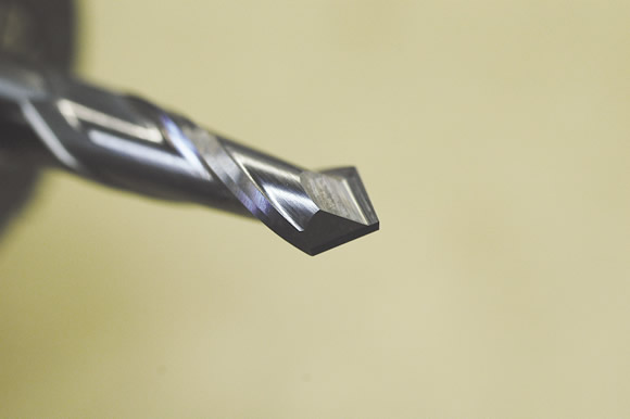
Drill-point endmills enable you to drill, mill and chamfer.
■ If you are planning or rearranging your CNC shop, be sure to include a water hose bib near the machines. Machines that operate all day long lose a significant amount of coolant to evaporation. This can be made up by adding water or a makeup solution of your water-based coolant to maintain the correct concentration.
■ Plumb a quick disconnect in line with your coolant line. If you make a short hose with a spray nozzle, it can be used to wash the inside of a machine after a job. This also makes it easier to steal some coolant from another machine in a pinch.
■ Apply cutting tools as long as possible to reduce cycle times. You can drill, mill and chamfer, for example, with a drill-point endmill. Sometimes a subtle change in tool selection will allow a tool to be used for several operations, eliminating the need for tool changes and noncutting time. This tip is valid even for rapid tool changes. Vertical machining centers typically have less-than-stellar spindle utilization, so anything you can do to keep the tool in the cut is a good thing.
■ A trick for separating multiple ganged parts involves applying a 90° chamfer mill or drill-point endmill to follow a contour that will be the parting line between the parts. Leave 0.001 " to 0.003 " of material at the bottom for an easy break line on the back of the ganged parts. Then, you can easily snap off the parts and insert them in pocketed soft jaws for second-side operations.
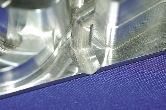
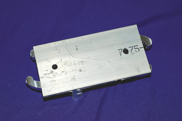
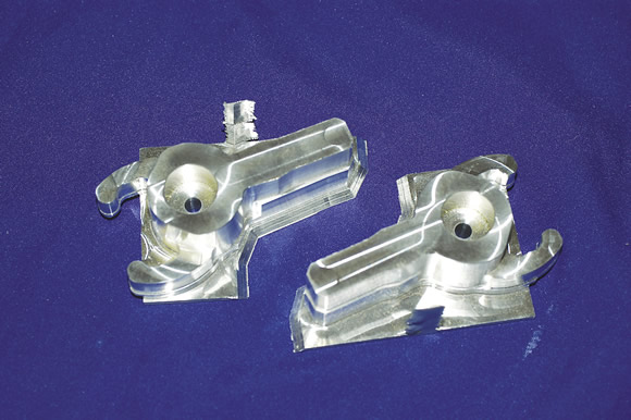
Top: A trick for separating multiple ganged parts involves applying a 90° chamfer mill or drill-point endmill to follow a contour that will be the parting line between the parts. Middle: Leave 0.001 " to 0.003 " of material at the bottom of the contour path for an easy break line on the back of the ganged parts. Bottom: Then, you can easily snap off the parts.
■ When circular interpolating, use a boring head to achieve the roundest possible holes. Single-point boring is still the most accurate method for achieving true position and hole roundness. Use single-point boring for precision bearing bores and where critical true position is required, such as with gear meshes and linear bearing bores.
■ If you’re having problems with hole roundness or true position when circular interpolating, try slowing the feed rate for the finishing pass to even out the quadrant mismatches. Even with high-speed controls, this trick will sometimes give you more consistent results. If your plug gage rocks in one direction when you test a hole, it is a sign the hole is not as round as it could be.
■ You can use out-of-roundness to your advantage. For sliding fits, where sliding parts are fitted together, a few tenths of out-of-roundness provides an air vent for a blind-hole or a place for lubricant to reside.
■ Keep a machine-dedicated logbook at each machine and CAM station to record problems and maintenance practices, among other notes. It also provides a great place to store all the little quirky bits of information related to each machine, such as “check Y-axis limit switch if you get error 1234.” If you need to call outside help, the logbook can be a valuable source of machine history for the technician. If you record information such as metal-removal rates for different tool types, these logbooks can also be a great training aide. This information has become the gold standard of operations, helping at every level—from the shop floor to engineering and estimating. On that same note, read the logbooks occasionally and see what kinds of information are being recorded. If it’s worth writing, it’s probably worth reading.
■ Document and laminate company setup and operation procedures for each machine. This will pay big dividends when training new operators. Keep the length to one operation or task per sheet, and then title the sheets. Some examples include: setting tool offsets, restarting a program at a particular line and adjusting wear offsets.
■ You never seem to have as many tool totes as you’d like. I feel the available totes for CNC toolholders are overpriced, which makes stocking up on them painful for small shops. Our sheet metal shop made some totes from ⅛"-thick aluminum. They are more compact than commercial units and dirt cheap to make. A tote allows you to “kit” a job’s tools ahead of time or efficiently store the exact tools for a repeat job. I even haul these into the CAM area when programming to make sure I have everything thought out correctly. CTE
 About the Author: Tom Lipton is a career metalworker who has worked at various job shops that produce parts for the consumer product development, laboratory equipment, medical services and custom machinery design industries. He has received six U.S. patents and lives in Alamo, Calif. For more information, visit his blog at oxtool.blogspot.com and video channel at www.youtube.com/user/oxtoolco. Lipton’s column is adapted from information in his book “Metalworking Sink or Swim: Tips and Tricks for Machinists, Welders, and Fabricators,” published by Industrial Press Inc., South Norwalk, Conn. The publisher can be reached by calling (888) 528-7852 or visiting www.industrialpress.com. By indicating the code CTE-2013 when ordering, CTE readers will receive a 20 percent discount off the book’s list price of $44.95.
Related Glossary Terms
- blind-hole
blind-hole
Hole or cavity cut in a solid shape that does not connect with other holes or exit through the workpiece.
- boring
boring
Enlarging a hole that already has been drilled or cored. Generally, it is an operation of truing the previously drilled hole with a single-point, lathe-type tool. Boring is essentially internal turning, in that usually a single-point cutting tool forms the internal shape. Some tools are available with two cutting edges to balance cutting forces.
- boring head
boring head
Single- or multiple-point precision tool used to bring an existing hole within dimensional tolerance. The head attaches to a standard toolholder and a mechanism permits fine adjustments to be made to the head within a diameter range.
- centers
centers
Cone-shaped pins that support a workpiece by one or two ends during machining. The centers fit into holes drilled in the workpiece ends. Centers that turn with the workpiece are called “live” centers; those that do not are called “dead” centers.
- computer numerical control ( CNC)
computer numerical control ( CNC)
Microprocessor-based controller dedicated to a machine tool that permits the creation or modification of parts. Programmed numerical control activates the machine’s servos and spindle drives and controls the various machining operations. See DNC, direct numerical control; NC, numerical control.
- computer-aided manufacturing ( CAM)
computer-aided manufacturing ( CAM)
Use of computers to control machining and manufacturing processes.
- coolant
coolant
Fluid that reduces temperature buildup at the tool/workpiece interface during machining. Normally takes the form of a liquid such as soluble or chemical mixtures (semisynthetic, synthetic) but can be pressurized air or other gas. Because of water’s ability to absorb great quantities of heat, it is widely used as a coolant and vehicle for various cutting compounds, with the water-to-compound ratio varying with the machining task. See cutting fluid; semisynthetic cutting fluid; soluble-oil cutting fluid; synthetic cutting fluid.
- endmill
endmill
Milling cutter held by its shank that cuts on its periphery and, if so configured, on its free end. Takes a variety of shapes (single- and double-end, roughing, ballnose and cup-end) and sizes (stub, medium, long and extra-long). Also comes with differing numbers of flutes.
- feed
feed
Rate of change of position of the tool as a whole, relative to the workpiece while cutting.
- gang cutting ( milling)
gang cutting ( milling)
Machining with several cutters mounted on a single arbor, generally for simultaneous cutting.
- milling
milling
Machining operation in which metal or other material is removed by applying power to a rotating cutter. In vertical milling, the cutting tool is mounted vertically on the spindle. In horizontal milling, the cutting tool is mounted horizontally, either directly on the spindle or on an arbor. Horizontal milling is further broken down into conventional milling, where the cutter rotates opposite the direction of feed, or “up” into the workpiece; and climb milling, where the cutter rotates in the direction of feed, or “down” into the workpiece. Milling operations include plane or surface milling, endmilling, facemilling, angle milling, form milling and profiling.
- milling machine ( mill)
milling machine ( mill)
Runs endmills and arbor-mounted milling cutters. Features include a head with a spindle that drives the cutters; a column, knee and table that provide motion in the three Cartesian axes; and a base that supports the components and houses the cutting-fluid pump and reservoir. The work is mounted on the table and fed into the rotating cutter or endmill to accomplish the milling steps; vertical milling machines also feed endmills into the work by means of a spindle-mounted quill. Models range from small manual machines to big bed-type and duplex mills. All take one of three basic forms: vertical, horizontal or convertible horizontal/vertical. Vertical machines may be knee-type (the table is mounted on a knee that can be elevated) or bed-type (the table is securely supported and only moves horizontally). In general, horizontal machines are bigger and more powerful, while vertical machines are lighter but more versatile and easier to set up and operate.
- milling machine ( mill)2
milling machine ( mill)
Runs endmills and arbor-mounted milling cutters. Features include a head with a spindle that drives the cutters; a column, knee and table that provide motion in the three Cartesian axes; and a base that supports the components and houses the cutting-fluid pump and reservoir. The work is mounted on the table and fed into the rotating cutter or endmill to accomplish the milling steps; vertical milling machines also feed endmills into the work by means of a spindle-mounted quill. Models range from small manual machines to big bed-type and duplex mills. All take one of three basic forms: vertical, horizontal or convertible horizontal/vertical. Vertical machines may be knee-type (the table is mounted on a knee that can be elevated) or bed-type (the table is securely supported and only moves horizontally). In general, horizontal machines are bigger and more powerful, while vertical machines are lighter but more versatile and easier to set up and operate.
- parting
parting
When used in lathe or screw-machine operations, this process separates a completed part from chuck-held or collet-fed stock by means of a very narrow, flat-end cutting, or parting, tool.
Author

Tom Lipton is a career metalworker from the San Francisco Bay area who has worked at various job shops. For more information, visit his blog and YouTube video channel.