Still more tips for a manual mill

Author Tom Lipton
Published
February 01, 2013 - 10:30am

Continuing and concluding the theme of my previous two columns, this month’s installment provides additional tips for enhancing the operation of a manual milling machine.

• For working on large plates, make a couple of spreader bars. The spreader bars have counterbored bolt holes on the same centers as the T-slots. Make the spreader bars out of something relatively soft so they can be sacrificial.

• Rounding the corners of a standard drill bit with a honing stone enables the drill to impart a finer hole finish. This is a sneaky way to get around not having an odd reamer size. You can also manually grind a twist drill a bit off-center to have it cut a whisker larger.

Ch06.Fig046.Lipton.DSC_3451.tif
All images courtesy T. Lipton

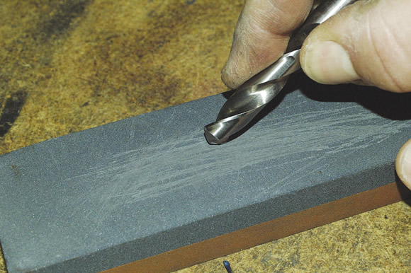
Use a honing stone to round corners on a drill to impart a finer hole finish when you don’t have an odd-size reamer.

Ch06.Fig049.Lipton.DSC_7541.tif

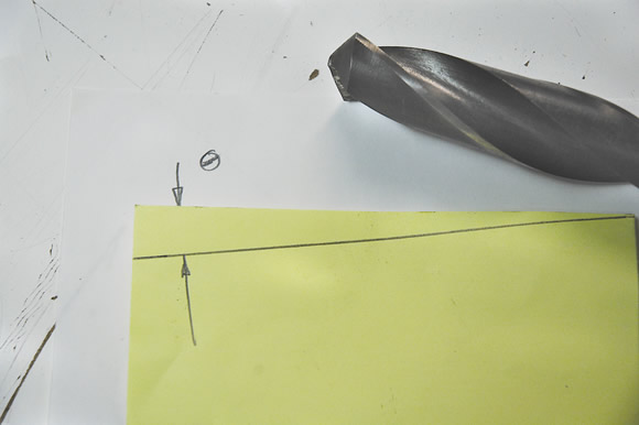
A slip of paper can be used to measure and indicate the back clearance, or relief, angle on a drill bit.

Ch06.Fig074.Lipton.DSC_2300.tif

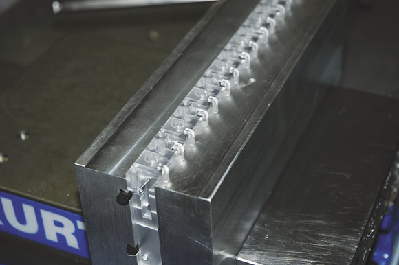
A cutoff piece or O-ring cord stock provides the right amount of squeeze and friction to securely hold multiple parts.

Ch06.Fig064.Lipton.DSC_0091.tif

You can use a drill chuck as a hand tapping guide if you leave the collet loose.

Ch06.Fig076.Lipton.DSC_2863.tif

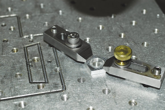
Strap clamps hold a small part on a subplate.

• A simple way to measure the back clearance, or relief, angle of a hand-ground drill bit is to use a little slip of paper. Wind the paper around the cylindrical part of the drill body and mark the point where the corner meets the edge of the paper. The angle formed by these points is the clearance angle.

• With an oversize table on a vertical mill, you can have more than one setup on the machine. Wipe the dovetails clean all the way to the ends of the travels and make use of that extra work envelope.

Put a short wrench on the vise to keep apprentices from overtightening setups. Use the clock method to describe the handle position. Tell them, “Tighten this to 3:00 exactly. Not 2:30 or 3:30.”

• You can use a drill chuck as a hand tapping guide if you leave the collet loose. Don’t forget to lift it up before you move to the next hole.

Get a cheap air ratchet for changing chuck and vise jaws. Replace the mounting screws with shorter ones to reduce spinning time. Be sure to take any cutting tools out of the spindle because the air ratchet can buck your hand into the tool if you’re not ready for the torque reaction.

Use some soft aluminum filler rod to help secure multiple parts. The soft, round wire squeezes down and makes up for the small differences in part width. This trick works best on hard parts, such as ones made of stainless steel, that require a fair amount of clamping pressure. Vertically position the soft wire for multiple stacked parts.

• Using a standard dovetail O-ring groove cut into a soft jaw face is another great trick for securely holding multiple parts. A cutoff piece or O-ring cord stock provides the right amount of squeeze and friction to hold the parts. You can also use different O-ring materials for different types of part holding.

One of the best things I ever made was a 6 "×6 " subplate with small strap clamps for holding small parts. You can also screw a parallel or a sheet metal V-plate to the subplate as a fence when you are making multiple parts.

• For accurate true position location, drill undersized and then use a single-point boring tool to establish the true centerline of the hole. After a light cleanup, cut with the boring head, finish ream the hole to size. As an alternative, drill and follow with an endmill plunge. CTE

About the Author: Tom Lipton is a career metalworker who has worked at various job shops that produce parts for the consumer product development, laboratory equipment, medical services and custom machinery design industries. He has received six U.S. patents and lives in Alamo, Calif. Lipton’s column is adapted from information in his book “Metalworking Sink or Swim: Tips and Tricks for Machinists, Welders, and Fabricators,” published by Industrial Press Inc., New York. The publisher can be reached by calling (888) 528-7852 or visiting www.industrialpress.com. By indicating the code CTE-2013 when ordering, CTE readers will receive a 20 percent discount off the book’s list price of $44.95.

Related Glossary Terms

  • boring

    boring

    Enlarging a hole that already has been drilled or cored. Generally, it is an operation of truing the previously drilled hole with a single-point, lathe-type tool. Boring is essentially internal turning, in that usually a single-point cutting tool forms the internal shape. Some tools are available with two cutting edges to balance cutting forces.

  • boring head

    boring head

    Single- or multiple-point precision tool used to bring an existing hole within dimensional tolerance. The head attaches to a standard toolholder and a mechanism permits fine adjustments to be made to the head within a diameter range.

  • centers

    centers

    Cone-shaped pins that support a workpiece by one or two ends during machining. The centers fit into holes drilled in the workpiece ends. Centers that turn with the workpiece are called “live” centers; those that do not are called “dead” centers.

  • chuck

    chuck

    Workholding device that affixes to a mill, lathe or drill-press spindle. It holds a tool or workpiece by one end, allowing it to be rotated. May also be fitted to the machine table to hold a workpiece. Two or more adjustable jaws actually hold the tool or part. May be actuated manually, pneumatically, hydraulically or electrically. See collet.

  • clearance

    clearance

    Space provided behind a tool’s land or relief to prevent rubbing and subsequent premature deterioration of the tool. See land; relief.

  • collet

    collet

    Flexible-sided device that secures a tool or workpiece. Similar in function to a chuck, but can accommodate only a narrow size range. Typically provides greater gripping force and precision than a chuck. See chuck.

  • cutoff

    cutoff

    Step that prepares a slug, blank or other workpiece for machining or other processing by separating it from the original stock. Performed on lathes, chucking machines, automatic screw machines and other turning machines. Also performed on milling machines, machining centers with slitting saws and sawing machines with cold (circular) saws, hacksaws, bandsaws or abrasive cutoff saws. See saw, sawing machine; turning.

  • endmill

    endmill

    Milling cutter held by its shank that cuts on its periphery and, if so configured, on its free end. Takes a variety of shapes (single- and double-end, roughing, ballnose and cup-end) and sizes (stub, medium, long and extra-long). Also comes with differing numbers of flutes.

  • gang cutting ( milling)

    gang cutting ( milling)

    Machining with several cutters mounted on a single arbor, generally for simultaneous cutting.

  • milling

    milling

    Machining operation in which metal or other material is removed by applying power to a rotating cutter. In vertical milling, the cutting tool is mounted vertically on the spindle. In horizontal milling, the cutting tool is mounted horizontally, either directly on the spindle or on an arbor. Horizontal milling is further broken down into conventional milling, where the cutter rotates opposite the direction of feed, or “up” into the workpiece; and climb milling, where the cutter rotates in the direction of feed, or “down” into the workpiece. Milling operations include plane or surface milling, endmilling, facemilling, angle milling, form milling and profiling.

  • milling machine ( mill)

    milling machine ( mill)

    Runs endmills and arbor-mounted milling cutters. Features include a head with a spindle that drives the cutters; a column, knee and table that provide motion in the three Cartesian axes; and a base that supports the components and houses the cutting-fluid pump and reservoir. The work is mounted on the table and fed into the rotating cutter or endmill to accomplish the milling steps; vertical milling machines also feed endmills into the work by means of a spindle-mounted quill. Models range from small manual machines to big bed-type and duplex mills. All take one of three basic forms: vertical, horizontal or convertible horizontal/vertical. Vertical machines may be knee-type (the table is mounted on a knee that can be elevated) or bed-type (the table is securely supported and only moves horizontally). In general, horizontal machines are bigger and more powerful, while vertical machines are lighter but more versatile and easier to set up and operate.

  • milling machine ( mill)2

    milling machine ( mill)

    Runs endmills and arbor-mounted milling cutters. Features include a head with a spindle that drives the cutters; a column, knee and table that provide motion in the three Cartesian axes; and a base that supports the components and houses the cutting-fluid pump and reservoir. The work is mounted on the table and fed into the rotating cutter or endmill to accomplish the milling steps; vertical milling machines also feed endmills into the work by means of a spindle-mounted quill. Models range from small manual machines to big bed-type and duplex mills. All take one of three basic forms: vertical, horizontal or convertible horizontal/vertical. Vertical machines may be knee-type (the table is mounted on a knee that can be elevated) or bed-type (the table is securely supported and only moves horizontally). In general, horizontal machines are bigger and more powerful, while vertical machines are lighter but more versatile and easier to set up and operate.

  • parallel

    parallel

    Strip or block of precision-ground stock used to elevate a workpiece, while keeping it parallel to the worktable, to prevent cutter/table contact.

  • reamer

    reamer

    Rotating cutting tool used to enlarge a drilled hole to size. Normally removes only a small amount of stock. The workpiece supports the multiple-edge cutting tool. Also for contouring an existing hole.

  • relief

    relief

    Space provided behind the cutting edges to prevent rubbing. Sometimes called primary relief. Secondary relief provides additional space behind primary relief. Relief on end teeth is axial relief; relief on side teeth is peripheral relief.

  • tapping

    tapping

    Machining operation in which a tap, with teeth on its periphery, cuts internal threads in a predrilled hole having a smaller diameter than the tap diameter. Threads are formed by a combined rotary and axial-relative motion between tap and workpiece. See tap.

  • twist drill

    twist drill

    Most common type of drill, having two or more cutting edges, and having helical grooves adjacent thereto for the passage of chips and for admitting coolant to the cutting edges. Twist drills are used either for originating holes or for enlarging existing holes. Standard twist drills come in fractional sizes from 1¼16" to 11¼2", wire-gage sizes from 1 to 80, letter sizes A to Z and metric sizes.

  • work envelope

    work envelope

    Cube, sphere, cylinder or other physical space within which the cutting tool is capable of reaching.

Author

Tom Lipton is a career metalworker from the San Francisco Bay area who has worked at various job shops. For more information, visit his blog and YouTube video channel.