Spindle bearings support the spindle in the housing and transmit cutting forces to the machine structure. The bearings are intended to hold the spindle accurately in position.
If the spindle was a rigid body, and the bearings were infinitely stiff, kinematically the bearings would restrict 5 of the 6 degrees of freedom, preventing all motion except rotation about the long spindle axis. In reality, the spindle is not a rigid body, because it can bend. The bearings are not infinitely rigid, but act as stiff springs supporting the spindle.
It is important for the bearings to be very stiff, because the stiffer they are, the more accurate the machine is and the less likelihood there is for chatter. Setting and maintaining the preload in spindle bearings (keeping the balls under significant compression) is essential, because if the preload is released, bearing stiffness drops by a factor of two. To see why, examine Figure 1, which shows a cross section of the spindle (blue) and the forces (red) created by the compression preloading of two opposing balls.
We are ignoring the other balls for now and assuming that the force in the spring is linearly proportional to the amount the balls are squeezed (F = ky). In reality, the balls are springs that get stiffer the harder they are squeezed, but as long as the displacement is small, our approximation is not a problem.
Without an applied external load (white arrow), the forces produced on the spindle by the balls are balanced, and the spindle is centered in the housing. In this case, the sum of the forces in the vertical direction is:
Fbottom - Ftop = kΔ - kΔ = 0.
This means the spindle will not move up or down.
If we apply an external load to cause a small displacement in the vertical direction y, the situation is shown in the bottom part of Figure 1. The external force releases a little of the preload on the bottom and slightly increases the preload on the top. In that case, the sum of the forces in the vertical direction, which still sum to 0 so the spindle does not move up or down, is:
Fbottom + Fexternal - Ftop = k(Δ-y) + Fexternal - k(Δ+y) = 0.
That can be written as:
kΔ - ky + Fexternal - kΔ - ky = 0, or
Fexternal = 2ky.
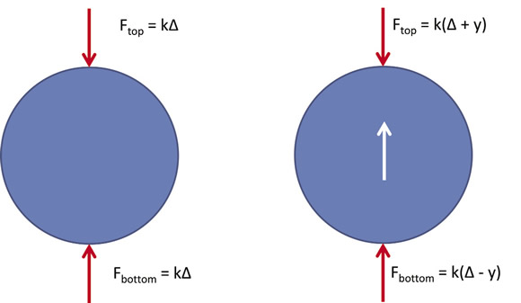
Figure 1. A preloaded spindle with no external load (left) and with an applied external load (right).
Even though one ball is being compressed, and one is being released, the stiffness for the balls adds together (k + k = 2k) as long as they both stay in contact with the spindle. The stiffness of the other balls in the bearing only contributes partially to the bearing stiffness in the vertical direction. Because the forces in those balls act radially, they only have a smaller component of force-carrying capacity in the vertical direction. However, each ball has a matching ball on the opposite side, and the same rule applies. As long as all of the balls are in contact, the stiffness is increased both by the balls being compressed and by those being released by the external force.
If the preload is lost, the spindle stiffness is reduced by a factor of two. If the external force is large enough to make y larger than Δ, all of the balls on the bottom side of the spindle lose contact with the spindle and can no longer contribute to spindle stiffness.
Obviously, a higher preload is preferred, because that means a larger external force can be carried before the stiffness drops. However, there is a limit created by heat generation. As each ball rolls, the preload force alternately compresses and releases the ball. Those small motions generate heat, and the heat generated by friction between the balls and races increases with the preload.
Maintaining the preload for stiffness and accuracy while simultaneously managing the heat generated by the preload is a great challenge for machine tool spindle designers. CTE
About the Author: Dr. Scott Smith is a professor and chair of the Department of Mechanical Engineering at the William States Lee College of Engineering, University of North Carolina at Charlotte, specializing in machine tool structural dynamics. Contact him via e-mail at [email protected].Related Glossary Terms
- chatter
chatter
Condition of vibration involving the machine, workpiece and cutting tool. Once this condition arises, it is often self-sustaining until the problem is corrected. Chatter can be identified when lines or grooves appear at regular intervals in the workpiece. These lines or grooves are caused by the teeth of the cutter as they vibrate in and out of the workpiece and their spacing depends on the frequency of vibration.
- degrees of freedom
degrees of freedom
Number of axes along which a robot, and thus the object it is holding, can be manipulated. Most robots are capable of maneuvering along the three basic Cartesian axes (X, Y, Z). More sophisticated models may move in six or more axes. See axis.
- stiffness
stiffness
1. Ability of a material or part to resist elastic deflection. 2. The rate of stress with respect to strain; the greater the stress required to produce a given strain, the stiffer the material is said to be. See dynamic stiffness; static stiffness.
Author
Dr. Scott Smith is a professor and chair of the Department of Mechanical Engineering at the William States Lee College of Engineering, University of North Carolina at Charlotte, specializing in machine tool structural dynamics. Contact him via e-mail at [email protected].

Click on the author to view all of their articles!