Speed Tapping
Speed Tapping
Tap and tapholder manufacturers have introduced technology to speed up the inherently slow tapping process. This article reviews a number of innovations, including tension/compression holders for rigid tapping, self-reversing tapping heads and quick-change tapholders.
Users discover the technology they need to boost tapping rpm.
Tapping has long frustrated manufacturing engineers, because, traditionally, it has been one of the slowest operations on their production lines. Automotive plants, in particular, put a premium on speed. In their aggressive pursuit of faster cycle times and increased flexibility, automotive engineers have switched from transfer lines to high-speed manufacturing cells using CNC machines capable of running at high speed. Increasing the speed of an operation can produce spectacular results. But, until recently, the process engineers couldn't take advantage of their machines' high-speed capabilities when it came to tapping.
To satisfy users' demands for tapping cycles that are more in line with other machining cycles, manufacturers of taps and tapholders have introduced a number of innovations, including thread mills and thrillers. Users have found this new technology most efficient on larger thread sizes. Unfortunately, these are not the sizes automakers typically use for their components. Few of the 80 or so holes that automotive manufacturers tap in a four-cylinder engine block, for example, are larger than 12mm.
The need for high-speed tapping solutions in smaller thread sizes has led to further developments in tap, tapholder, and tapping-head designs. This new technology has made it possible for the development of a high-speed tap (which its manufacturer calls a "full-speed tap") engineered to work at speeds more than six times faster than conventional taps. The improved performance is due to the use of premium cobalt-enriched tool steels, innovative cutting geometries, and flute designs enhanced with through-coolant capability and advanced surface coatings.
With the use of these new tools, shops have been able to increase their tapping speeds. But with the boost in rpm, new concerns have arisen. Users have found that tapping at higher speeds with rigid tapholders accentuates any mismatch between the synchronous feed and the tap pitch.
Mismatches occur because there is no absolute control in a rigid tap cycle. This is not to say that CNCs are all bad. In fact, controls today are better than they have ever been. However, some amount of uncertainty of movement is to be expected no matter how accurate a machine tool may be, because all electrical, hydraulic, and mechanical movements are prone to errors.
The amount of these errors on most CNC machines is minimal, but there is always some degree of uncertainty. In general, the errors that affect a CNC machine can be attributed to wear, backlash, the results of accumulated tolerance, and calibration or the lack of calibration. Exhaustive studies have shown that, even under the best of circumstances, these small faults can lead to errors in synchronizing spindle feed, speed, and reversal. To some degree, these synchronization errors can be controlled through proper maintenance, but they can't be eliminated entirely.
The errors that do occur are enough to influence tapping performance at higher speeds, especially as the tap reverses. The most serious problems caused by synchronization errors are a reduction in tap life and poor thread quality. Tap life is affected to a degree directly proportional to the amount of error in the CNC machine. Thread quality suffers because the mismatch between spindle speed and tap pitch causes the tap to drag (rub) while backing out. The dragging leads to loading (cold pressure welding), and this produces rough and torn threads.
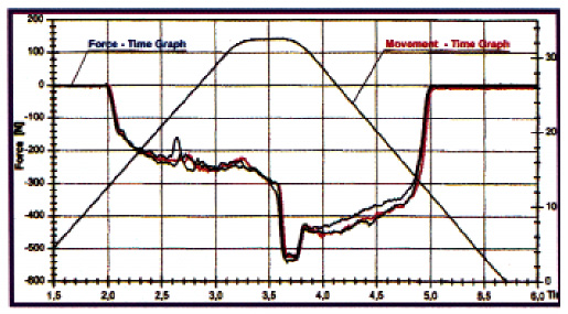
Fig 1: This graph plots the cutting forces generated in three trials by a tap with M10 threads cutting in synchronous mode. The sharp increase in negative forces in the middle of the graph was caused by the spindle reversal.In a comprehensive study sponsored by Emuge Corp., Northborough, MA, and conducted at the University in Kassel, Germany, researchers measured the extreme cutting forces that these synchronization errors generate during a rigid tapping cycle. Figure 1 is a plot of these measurements. As the graph shows, a sharp increase in negative forces occurred at the point that tap rotation was reversed (between 3.5 and 3.8 seconds). The forces remained high during the entire time the tap was backed out of the tapped hole.
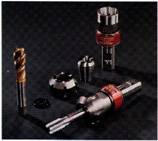
Fig 2: These Softsynchro tapholders, offered by EMuge and Tapmatic, feature a slight amount of tension/compression to compensate for a CNC machine's small inaccuracies.
To eliminate tap drag and rubbing, and ultimately, to create higher quality threads and increase tap life, a tapholder was designed with an elastic spring element that offers a slight amount (0.5mm) of tension/compression to compensate for minute machine-feed errors. This rigid tapholder grips the tap by means of an ER-GB-style collet and can be used with standard rigid tap cycles just as solid-type holders are used (Figure 2).
The new tapholder's ability to reduce cutting forces can be seen in Figure 3, which plots additional test runs by the researchers in Kassel, Germany. The red line on the graph shows the cutting forces generated as a 10mm tap - held in a rigid holder and mounted in a new
machine tool - tapped a hole in synchronized mode. This plot shows the same spike in forces at the moment of spindle reversal as the spike that appeared in Figure 1. After recording the forces with the tap in a rigid holder, the researchers placed the same tap in a tapholder with 0.5mm tension/compression. The researchers then mounted the tap and holder in the same machine tool and tapped another hole. The blue line on
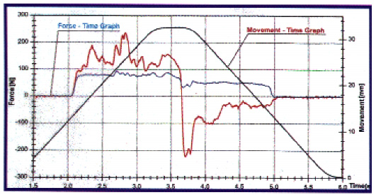
Fig. 3: As can be seen in this comparison, a tap held in a helder with 0.5mm tension/compression (the blue line) generates fewer negative cutting forces than a tap held in a conventional tapholder(the red line).(Click for larger image)Figure 3 shows the forces generated during this run. As can be seen by comparing the blue line with the red line, the forces are much lower and steadier.
In further testing, the researchers looked at the relationship between the tap's helical pitch and the cutting forces generated. They discovered that the compression forces changed to tension forces when a tap with increased helical pitch was used. The researchers also found that a toolholder with 0.5mm tension/compression could reduce these tension forces as well as it could reduce compression forces.
From these tests, the researchers concluded that a tapholder with 0.5mm tension/compression could: Reduce axial forces on the tap. Distribute axial forces evenly on the tap during the tapping and reversing process. Eliminate the spike in axial forces typically seen when the tap is reversed. Reduce the forces caused by the use of taps with greater helical pitch.
For the user, the elimination or reduction of these forces means a significant improvement in synchronous tapping performance. Specifically, the use of a tapholder with 0.5mm tension/ compression will: Compensate for minimal pitch differences between the machine's synchronous spindle and the tap. Reduce the axial forces at the tap flanks, optimizing tool life. Prevent the tap from miscutting the threads during the reverse phase. Allow the use of an internal coolant supply up to 750 psi.
Reversing Another Problem
As the tests in Germany have shown, the use of a tapholder with slight tension/compression can eliminate problems caused by a CNC machine's synchronization errors when tapping at high speeds. However, these tapholders cannot correct for problems associated with machine reversal. These problems can have a more significant impact on tapping performance than synchronization problems, especially in high-production applications.
Every other machining operation (milling, boring, and drilling, for instance) can be performed in one direction, but tapping takes two spindle reversals per tapped hole. It's a basic law of physics that a rotating mass - in this case, the machine spindle - must slow down and stop before reversing and accelerating. Because of this deceleration and acceleration, the tap is seldom running at the programmed or indicated machine speed or the speed recommended by the tap manufacturer. That's why a machinist who is performing synchronous-feed tapping must work with average speed rather than indicated machine speed.
A machinist can easily measure the impact acceleration and deceleration will have on the tapping cycle time. First, the time it takes to tap one hole in synchronous mode is measured. This measurement is then compared to a calculation of the time the tapping cycle should take given the programmed speed. This is figured using the formula:
| total distance | = time in minutes |
| feed rate (ipm) | (multiply by 60 to convert to seconds) |
Theoretically, the feed rate should be rpm multiplied by pitch for metric taps or rpm divided by pitch for inch taps. Inevitably, the actual tapping cycle will prove to be longer than the calculated cycle. The difference between the two times represents the seconds consumed by spindle dwell, acceleration, and deceleration.
Besides this loss of efficiency, synchronous feed also breaks a basic rule of good machining: Never reduce rpm in the middle of the cut. Taps wear prematurely when they are subjected to fluctuating speeds.
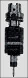
Fig. 4: A high speed, self-reversing tapping attachment, such as this unit offered by Tapmatic and Emuge, can eliminate time-consuming spindle reversals.The new full-speed tap designs work best when the high speeds the tap manufacturer recommends are maintained throughout the cut. This means that the tap constantly rotates at the full indicated machine speed and is reversed instantly with no deceleration, acceleration, or dwells. Constant speed is accomplished by employing a compact self-reversing tapping attachment between the machine spindle and the tap (Figure 4). The tapping attachment does the reversing while the machine continues to run in one direction.
Eliminating spindle reversals improves tapping-cycle performance in a number of ways:
Faster cycle times. With synchronous feed and two spindle reversals, the machine spindle is in a state of constant acceleration and deceleration while tapping standard-depth holes (1 to 1 1/2 diameters). Depending on the speed of the spindle, it may not reach its full rpm before it must begin decelerating in preparation for the reversal at the bottom of the hole. Where the acceleration and deceleration planes cross is the maximum speed the spindle will be able to reach during the tapping cycle. This point on most full-size machining centers can be as low as 1200 rpm. With the use of a self-reversing tapping attachment, the spindle can exceed the 1200-rpm limit and run at the programmed rpm, because acceleration and deceleration are eliminated. With the spindle turning faster, cycle time is reduced over synchronous-feed cycle times that require two spindle reversals.
Increased tap life. By tapping at a constant surface speed, the machine spindle can achieve and maintain the speed recommended by the tap's manufacturer. This is the speed for which the tap was designed, and it is the speed at which tap performance and life are optimized. Some end users have reported 10 times longer tap life with the use of a self-reversing tapping attachment that allows these speeds to be reached and maintained.
Less wear and tear on the machine tool spindle. Any part of a CNC machine that is in motion during spindle reversal will wear over time. When a machine reverses, some parts will be subjected to more strain than others will, but the components that will be affected most are the spindle motor, spindle bearings, and the spindle itself. How quickly this strain will begin to affect the machine's performance will depend on factors such as the speed of the tapping operation, the quality of the machine, the machine's calibration, preventive maintenance, and the number of reversals per shift.
When a self-reversing tapping head is used, it will absorb this strain. A renewable drive element is built into some self-reversing heads to bear most of this strain. This component costs about the same as a good tap and can be replaced in five minutes or less with no machine down time. The component's predictable wear qualities and its ease of replacement allow the shop's personnel to schedule programmed maintenance for the tapping head based on the severity of the job.
The Big Question
Some shops may be wondering when to use a self-reversing tapping attachment and when to use rigid tapping. If a job shop is primarily performing other operations, such as boring, milling, or drilling, and its machinists are tapping only a few holes an hour, it may choose to use rigid tapping. However, in a high-production application, where parts such as engine blocks, transmission cases, water pumps, or other components that require several tapped holes are being machined, a self-reversing tapping attachment will provide significant improvements in performance.
The time and money saved by a major automotive manufacturer when it changed over to self-reversing tapping heads is typical. The manufacturer was using its CNC machines to drill and tap holes in throttle bodies. In this high-production situation, the machines were tapping a large number of holes per hour. The strain of continual reversals took its toll on the spindles and spindle motors. These components had to be replaced on a yearly basis at a cost of $25,000 per machine. Since the manufacturer began using self-reversing tapping attachments, it has not had to replace a spindle or spindle motor in five years. The switch to a self-reversing head also shaved four seconds per part off of the tapping cycle even though the spindle speed remained the same, and tap life increased from 2000 holes to 12,000 holes per tap.
Eliminating Pullout Problems
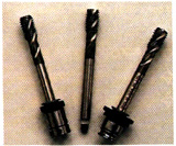
Fig. 5: These Emuge Full-Speed taps for high-speed tapping are mounted in Tapmatic E-lock tap adapters, which can hold the taps securely at speeds up to 4000 rpm.Quick-change tap adapters were widely used when high-production tapping was performed on transfer lines by multispindle machines. But these adapters have not been used with self-reversing tapping heads, because the adapters have been found to be unreliable at speeds above 1000 rpm. Instead, shops have had to use collets, nuts, and wrenches to secure their taps in self-reversing heads. With the recent introduction of the E-Lock quick-change system, which operates at speeds up to 4000 rpm, machinists now have the option of using a quick-change system with a self-reversing head (Figure 5).
The new adapters are interchangeable with other quick-change adapters. Special adapters that minimize the weight of the rotating spindle are available to fit self-reversing tapping attachments.
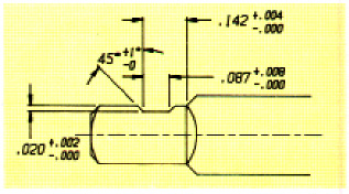
Fig. 4: A high speed, self-reversing tapping attachment, such as this unit offered by Tapmatic and Emuge, can eliminate time-consuming spindle reversals.The E-Lock system uses standard taps featuring a slight modification that can be performed in any shop (Figure 6). Modified taps also can be purchased off the shelf from some tap manufacturers. The E-Lock mechanism uses a spring-pin that locks securely into a ground notch on the square of the tap. This pin cannot be released unless the tap adapter is removed from the tapping attachment's quick-change spindle. While the pin is engaged in the tapholder, it is almost impossible for the tap to pull out.
The E-Lock system is one example of how manufacturers have responded to end users' needs with practical innovations. The technology that is now available--embodied in such products as E-Lock adapters, high-speed taps, tapholders with 0.5mm tension/compression, and self-reversing tapping attachments --gives users the tools they need to turn what was once one of the slowest operations on a production line into one of the fastest.
About the Authors
David Ridenour is national sales manager for Tapmatic Corp., Post Falls, ID. Peter Matysiak is president of Emuge Corp., Northborough, MA.