Newly developed monitoring and control systems give EDMs the brains to correct their own problems.
Machine tools are getting smarter all the time. Many of the tasks and functions that once were assigned to human operators are now being handled by the machines themselves. If this trend toward automation continues, the shop of the future may be equipped with machines that not only load and unload parts, tools, and programs on their own, but also evaluate their own performance in real time and correct problems on the fly before the problems lead to scrapped parts. These ultra-modern shops will still need EDMs to cut hard materials and complicated shapes. But like the other machines on the shop floor of the future, these EDMs also will have automated functions to meet the needs of users running operations with a minimum number of employees. Researchers at the University of Nebraska-Lincoln’s Nontraditional Manufacturing Research Center have laid the foundation for these advanced EDMs with their work on high-performance, automatic die-sinker- and wire-EDM control systems.
Controlling Spark Frequency
For wire EDMs, the researchers have been working on a control that can quickly optimize all parameters online. With these parameters maintained at an optimum level throughout the cut, the machine should be able to produce a higher quality machined surface faster and more accurately than a machine without such a control can produce.
The research center’s efforts have focused primarily on controlling the number of sparks per a unit of time, or sparking frequency, because this wire-EDM parameter has the most significant influence on speed, quality, and accuracy. Each spark is a short 1 to 3 microsecond burst of power. The frequency of these bursts depends on how long the current is off between bursts.
EDM manufacturers typically supply a database with their machines’ controllers to help operators select an optimal spark frequency based on the workpiece material and height. Once the user sets the machine to this frequency, the machine remains at this setting for the entire cutting process. However, in finish surface EDMing, this initial setting may not ensure proper performance for the entire operation. The optimal frequency may change because of changes in the workpiece height at the point of the cut or other random variations in the condition of the gap between the wire and the workpiece. If the spark frequency is not changed to respond to these new circumstances, temperatures can rise in segments of the wire, and eventually the wire will break. This problem is most likely to occur when wire-EDMing a thin workpiece, because the discharges are distributed on a narrower section of wire. The resulting uneven distribution of energy increases local temperatures, due to the variation of debris density in the gap.
Several manufacturers of wire EDMs are attempting to develop controls that can online monitor and control the spark frequency while the machine is cutting, but there are no machines on the market currently with such monitoring and control systems. The manufacturers are finding it difficult to design a system that can monitor changes in the workpiece’s height.
Figure 1: The components of a wire-EDM monitoring and control system.
Researchers at the Nontraditional Manufacturing Research Center have found an answer. They have developed a way for an EDM to gage a workpiece’s height, and they have incorporated this technology into a wire-EDM controller that works with a PC to measure and adjust the spark frequency in response to changing conditions. The control system consists of a PC, a gap monitor that plugs into one of the PC’s expansion slots, and a software package to evaluate incoming data about the gap and make the necessary changes in the spark frequency. Figure 1 is a diagram showing the components of the system and the direction of the monitoring and control signals between them.
The system is designed to work with a machine cutting steel or steel-alloy workpieces. While the workpiece is being EDMed, the system analyzes the spark frequency and machine speed and uses a mathematical model to translate this data into a measurement of workpiece height. The system can determine the workpiece height at the cut with an accuracy of 1mm. The spark frequency is then adjusted to an optimal level for the workpiece height just measured. Generally, the frequency will have to rise as the height of the workpiece increases. This gives the wire more power to cut through the thicker material.

Figure 2: The climbing line in graph 2A shows how the monitoring system was able to detect changes in workpiece height. The bottom line in graph 2B shows how the monitored and controlled spark frequency changed in response to changes in the workpiece height. The top line in 2B shows the corresponding changes the system made to the control frequency.
Figures 2A and 2B chart the data collected by the system during the EDMing of a workpiece with a profile that changed in height from 5mm to 26mm. The line in Figure 2A shows the system’s measurement of the workpiece height over time. In Figure 2B, the changes in the monitored and controlled spark frequency over the same amount of time are indicated by the lower line. The upper line indicates the frequency of the pulse used to govern the spark frequency. The two charts taken together show how the controller was able to maintain an optimal average spark frequency throughout the cut by smoothly increasing the frequency to follow the increase in workpiece height.
Arcs and Sparks
To improve the quality of die-sinker EDMing, the researchers at the Nontraditional Manufacturing Research Center looked for a way to detect and eliminate stable arcs between the electrode and the workpiece. These are arc discharges that occur repeatedly at the same location. They are undesirable because they can cause thermal damage to the workpiece surface. Graphite electrodes are especially susceptible to stable arcing. The arcs occur when flushing becomes difficult, especially during the machining of a deep cavity. The eroded chips and the carbon blacks generated by high temperatures due to discharges accumulate at a particular location in the gap. Stable arcing is not a severe problem with copper electrodes, but many EDM users in the United States prefer graphite electrodes, because they are easier to fabricate into complicated shapes, and they remove material at a higher rate.
Figure 3: Voltage and current waveforms of the five basic gap states.
A stable arc is one of five basic EDM gap states. The other states are “gap open,” “normal spark,” “transient arc,” and “short circuit” (Figure 3). The gap may be in any one of these states at any time because of the random nature of the EDM process. As long as the ratio of stable arcing to the other gap states remains low, the workpiece will suffer little damage. But when the proportion of stable arcing rises, the user must take corrective action.
The gap is in the “gap open” state while the dielectric fluid is breaking down, a period of time called the “ignition delay.” This “delay” ends when there is a discharge of current between the electrode and the workpiece, at which point the gap goes into one of the other four states. When the gap size is relatively large, the gap will be in the “gap open” state a larger proportion of the time. If the gap size is very small, the gap will be in the “short circuit” state more often. When the gap size is controlled properly, the rate of discharge, which is the sum of the “normal spark,” “transient arc,” and “stable arc” states, will be higher. As flushing conditions deteriorate, the discharge moves from sparking to arcing.
Most die-sinker EDM controllers are designed to look for an absence of a “gap open” state before a discharge, which would mean that there is no ignition-delay time; the current between the electrode and the workpiece is discharging immediately after it is applied. These controllers interpret the loss of an ignition-delay time to mean that harmful arcing is occurring and corrective action is needed. To correct the condition, the controller might adjust the servo reference voltage, the pulse off-time, or the amount of time the electrode is in the cut (jump-down time). However, researchers have discovered arcing damage even in applications that maintained a “gap open” state. A control strategy triggered by a loss of ignition-delay time would not respond in these situations. Because of this limitation, a controller using this strategy would not be able to address the random, shifting conditions that can occur during the die-sinker EDM process.
Another way to tell if the EDM is producing normal sparks or harmful arcing is to look for a high-frequency oscillation in the discharge voltage. A radio-frequency signal will always be a component of a normal spark. The researchers at the Nontraditional Manufacturing Research Center have used this strategy to develop a digital EDM gap monitor and an adaptive die-sinker-EDM control system. This monitoring system detects gap states and precisely measures the time ratios between the states it finds. This monitoring system can identify gaps in the “transient arc” state. Typically the gap moves from this state to the “stable arc” state. If the gap is in the “transient arc” state more often, it indicates the onset of gap pollution that will eventually lead to stable arcing. By detecting this early-warning signal, the controller can take corrective action before the workpiece is damaged.
Figure 4: The components of a monitoring and control system for die-sinker EDMs.
The control system uses an advanced, multiple-input, neural-network adaptive control strategy. The PC running the control system monitors all gap states by analyzing data from the monitoring system and generates control signals to modify machine parameters in real time. The parameter this system controls is jump-down time. When the system is in danger of harmful arcing, the controller reduces the jump-down time. This improves flushing conditions by increasing the time the electrode is retracted. Figure 4 shows the components of this system. The monitoring unit is separate from the PC, in which the digital measuring-and-control unit is installed.
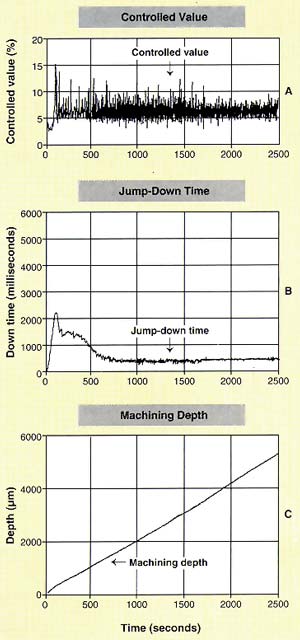
Figure 5: These graphs show the data recorded from a die-sinker EDM operation that incorporated adaptive control.
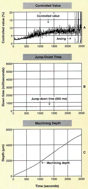
Figure 6: These graphs show the data recorded from a die-sinker EDM operation that did not have adaptive control.
Figures 5 and 6 show data from two machine operations during which deep cavities were EDMed. Figure 5 shows an operation using the adaptive control system. Figure 5A depicts the controlled value, which is a combination of the gap-state parameters that the monitoring system was detecting at any given time. The researchers found that for this operation a controlled value of 6% indicated a stable process. When the value went above this reference value, it was a sign of gap pollution.
The data recorded in the graphs of Figure 5 indicate that the gap had good flushing in the beginning of the operation. Figure 5B, which traces the jump-down time during the operation, shows that the good flushing conditions allowed the controller to keep the jump-down time high at the beginning. But as the machining depth increased, flushing deteriorated. In response, the controller gradually reduced the jump-down time to about 500 milliseconds. Figure 5C shows that the changes in jump-down time allowed the machining depth to increase smoothly without arcing damage.
Figure 6 records a process without adaptive control. For this operation, the researchers chose a jump-down time of 500 milliseconds for the entire operation. For the given setup, 500 milliseconds would be a somewhat aggressive setting, but it was chosen to match the value that the operation with adaptive control eventually came to. Without adaptive control, the controller could not change this jump-down time to respond to deteriorating flushing conditions. As a result, the controlled value, which is depicted in the top graph, gradually rises with the increase in machining depth. The spikes on the top graph show that unrecoverable arcing damage began at 35 minutes into the operation.
A Window on the Process
The software packages that accompany these wire- and die-sinker EDM monitors and controllers are built on the Microsoft Windows platform. They can be used with any interface hardware and EDM. Their flexibility allows users to integrate them into any system, including systems that incorporate data processing, fuzzy logic, neural-network control and analysis, servo control and modeling, identification of workpiece height (for wire EDM) or machining area (for die-sinker EDM), power-generator control, or other adaptive control algorithms. Users can incorporate their own programs as DLL (dynamic link library) files into these packages. EDM designers can use the software packages to simulate CNC and servo systems.
The wire-EDM package can use data from the gap monitor to assess the machine’s performance and alert users to problems. The software is designed to monitor the spark frequency and adjust it to maintain a preset level. Systems can be installed within the software to identify workpiece-height algorithms, provide adaptive control programs for the servo, and set control parameters for a variety of machines.
The die-sinker EDM software package can also be used as a diagnostic tool. The software can analyze data from the gap monitor to detect the five basic gap states. Using this information, the software can identify and correct problems. The data from an application also can be stored in a file for offline analysis.
The die-sinker EDM software also offers context-sensitive help. When machine operators, college students, or R&D engineers need advice on setting machine parameters or operating the software, they can call up the help window. The information offered will depend on the information currently displayed on the software screen. All the information was compiled by the software writers from research results, shop-floor experience, and teaching materials used in the center’s courses.
The hardware and software developed by the Nontraditional Manufacturing Research Center provide EDMs with the capabilities and functions modern shops are demanding. With adaptive controls that can detect and fix problems without operator intervention, these EDMs can be incorporated into lean and agile operations without placing a burden on a shop’s resources.
About the Authors
K.P. Rajurkar is the director and W.M. Wang is a research assistant professor at the Nontraditional Manufacturing Research Center, Industrial Management Systems Engineering Department, University of Nebraska-Lincoln.
Related Glossary Terms
- computer numerical control ( CNC)
computer numerical control ( CNC)
Microprocessor-based controller dedicated to a machine tool that permits the creation or modification of parts. Programmed numerical control activates the machine’s servos and spindle drives and controls the various machining operations. See DNC, direct numerical control; NC, numerical control.
- electrical-discharge machining ( EDM)
electrical-discharge machining ( EDM)
Process that vaporizes conductive materials by controlled application of pulsed electrical current that flows between a workpiece and electrode (tool) in a dielectric fluid. Permits machining shapes to tight accuracies without the internal stresses conventional machining often generates. Useful in diemaking.