Spindle units in machine tools have rotating and nonrotating components. Bearings in the stationary housing support the rotating spindle. The support bearings may be based on solid rolling elements, such as angular contact ball bearings, cylindrical roller bearings or tapered roller bearings. They may use a liquid, as in hydrostatic or hydrodynamic bearings, or a gas, as in aerostatic or aerodynamic bearings. The support bearings may even levitate the spindle in a magnetic field (magnetic bearings).
All of these bearings have precision components that contaminants can easily destroy. In addition, the inside of a spindle unit often houses the motor, tool-change mechanism, sensors and cooling systems. All internal elements must be protected from the spindle environment. Also, bearing lubrication should not be allowed to leak into the cutting zone, where it can contaminate coolant as tramp oil.
Spindles usually operate in hostile environments. They often rotate at high speeds, get hot and are exposed to chips, dust and smoke. There also may be coolant at high pressure and flow rates in the work zone. A critical component of spindle design—the seal—keeps these contaminants out of the spindle even under the harshest operating conditions.
If the spindle speed is only a few thousand rpm or so, a contact seal is probably sufficient. A sliding contact seal uses a soft material, such as a polymer or even cloth preloaded against a polished surface, to keep contaminants out. At low spindle speeds, the sliding contact does not generate much heat through friction. But in spindles that operate at higher speeds, the friction-generated heat becomes a problem, and a noncontact seal is required.
One type of noncontact seal is a labyrinth seal (Figure 1), named after the maze-like structure in Greek mythology designed by Daedalus to hold the Minotaur. Essentially, a labyrinth seal creates a long, narrow, torturous, open path that inhibits the passage of contaminants to the spindle interior and prevents small oil leaks, such as air-oil bearing lubrication.
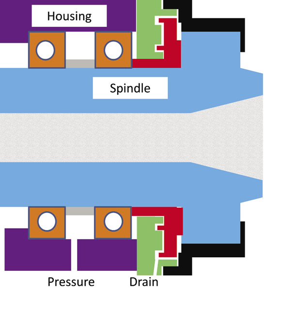
Figure 1. In this schematic of a labyrinth seal, the seal is comprised of the black, red and green rings. The black and red rings are attached to the spindle and rotate with it. The green ring is attached to the housing and is stationary.
In the figure, the labryrinth seal is comprised of the black, red and green rings. The black and red rings are attached to the spindle and rotate with it. The green ring is attached to the housing and is stationary. As the spindle rotates, any contaminants that penetrate the seal are thrown outward by the rotating black and red rings. The contaminants collect in the small cavity, or gullet, in the stationary green ring, where a drain or suction line is attached. The seal components are easy to assemble and have a small clearance.
An effective seal has a long, narrow path (white in the figure) that inhibits contaminants from reaching the bearing. If the gap is too small, deformation of the seal components due to centrifugal forces or differential thermal expansion—the spindle is often much hotter than the housing—causes the seal components to rub against each other. The resulting heat could damage the seal or cause the spindle to seize. If the gap is too large, contaminants from the cutting zone could reach the bearings and cause damage.
As a further precaution against contamination, the spindle interior is often pressurized. This enables a positive, outward airflow through the labyrinth seal. In this case, the air entering the spindle through the pressure port must be clean and dry so contaminants cannot reach the bearings while traveling with the pressurized air.
End users should follow a few simple guidelines to help the seal do its job. For example, the spindle should be rotating before starting the flood coolant. This enables the rotating rings to throw any penetrating coolant toward the drain. Similarly, the coolant should be turned off before the spindle is stopped. In addition, the spindle should be allowed to rotate for a few minutes after cutting stops and after the coolant is turned off to allow any contaminants to work their way to the suction port for removal.
It’s critical that coolant or pressurized air, such as from a cleaning gun, is not aimed directly at the open gap in the seal. Spindles equipped with a pressure port should not be run without pressurized air, and the air system should include a pressure regulator, filter and drier. The small channel is sensitive to damage and assembly errors, so users should frequently inspect the seal as part of regular maintenance procedures. CTE
About the Author: Dr. Scott Smith is a professor and chair of the Department of Mechanical Engineering at the William States Lee College of Engineering, University of North Carolina at Charlotte, specializing in machine tool structural dynamics. Contact him via e-mail at [email protected].
Related Glossary Terms
- clearance
clearance
Space provided behind a tool’s land or relief to prevent rubbing and subsequent premature deterioration of the tool. See land; relief.
- coolant
coolant
Fluid that reduces temperature buildup at the tool/workpiece interface during machining. Normally takes the form of a liquid such as soluble or chemical mixtures (semisynthetic, synthetic) but can be pressurized air or other gas. Because of water’s ability to absorb great quantities of heat, it is widely used as a coolant and vehicle for various cutting compounds, with the water-to-compound ratio varying with the machining task. See cutting fluid; semisynthetic cutting fluid; soluble-oil cutting fluid; synthetic cutting fluid.
- tramp oil
tramp oil
Oil that is present in a metalworking fluid mix that is not from the product concentrate. The usual sources are machine tool lubrication system leaks.
Author
Dr. Scott Smith is a professor and chair of the Department of Mechanical Engineering at the William States Lee College of Engineering, University of North Carolina at Charlotte, specializing in machine tool structural dynamics. Contact him via e-mail at [email protected].

Click on the author to view all of their articles!