Rigid Rules: General Industry Coverage
There are some tapping situations that call for a rigid tapholder and some that call for a length-compensating holder. Often the choice depends on the capabilities of the machine and the CNC driving the tap. This article discusses why a machinist might choose one type of tapholder or the other.
When tapping-tool users must decide between rigid and length-compensating tapholders, the choice often depends on the capabilities of the machine and CNC.
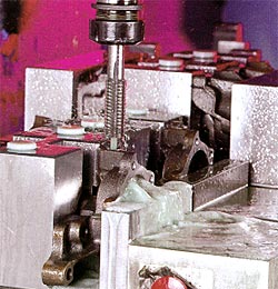
A through-coolant rigid tapholder is used on a vertical machining center to perform rigid tapping on an iron oil-pump housing.
When rigid tapping was introduced some five years ago, it was a hot-selling option on machining centers. Tapping-tool users found this function useful for a broad range of machining conditions. Now standard on most vertical and horizontal machining centers sold worldwide, rigid tapping is a natural complement to machines that are capable of increasingly higher speeds and feeds, faster axis travel, more precise performance, and broader versatility.
Although rigid tapping is a function of CNC and machine tool capabilities, the rigidity of the machine isn’t what makes this type of tapping rigid. The term “rigid” derives from the type of tapholders normally used in this operation. Such holders are rigid in the sense that they do not incorporate any mechanisms for length compensation during the course of the tapping cycle. Instead, they rely wholly on the machine tool itself to control the entire tapping cycle.
To provide such precise control, the CNC must be specifically programmed to meet two basic requirements. The first is to synchronize the spindle’s infeed with its rotational speed (rpm) and maintain this synchronization to the bottom of the tapped thread depth. This is equivalent to exactly mating the machine speed and feed to the thread pitch produced by the selected tap. All newer CNCs can be programmed for such synchronous tapping.
Only the latest CNCs meet the second requirement for rigid tapping, however. These controls provide complete control of the tapping cycle by eliminating overshoot, or “coast,” of the tap at the bottom of the thread during the spindle-braking portion of the tapping cycle. CNCs capable of rigid tapping can be programmed to anticipate the end of the downward tapping cycle and to time the activation of the spindle brake so that the tap is stopped completely at the programmed axial depth. This capability, in turn, enables free retraction of the tap from the hole. After the spindle has completely stopped, it reverses direction and rotates the tap out of the hole. Because the tap’s reversal begins at precisely the programmed thread depth, there should be no possibility of shaving the flank angles of the threads as the tap is retracted.
If these requirements can be met reliably by a CNC machine programmed for rigid tapping, a rigid tapholder is used. Theoretically, rigid tapping can be performed with any clamping device capable of holding a tap: The machine provides full control of the tapping cycle, and there’s no need for a tapholder that can compensate for feed/speed mismatches or coast at the bottom of the thread. Therefore, the tap can be held directly with an endmill adapter or other clamping device. These clamp-type holders, however, lack the quick-change capabilities of holders specifically designed for tapping.
Rigid Holders
Rigid tapholders offer some distinct advantages over length-compensating tapholders. The most significant benefit cited by customers who routinely use rigid holders is faster tapping cycles. With the high rigidity and precision control available in the latest machining centers that have rigid-tapping capabilities, users can run perfect tapping cycles at higher spindle speeds.
Another advantage of rigid tapholders is their compact size, since they do not incorporate a mechanism for length compensation that would be needed in the absence of full CNC tapping-cycle control. The shorter overhang of rigid holders permits operation within a small x-y-z envelope. Thus, in cases where height or table space is limited, such as with very large workpieces, rigid holders may be the solution. At the same time, the shorter tool overhang is consistent with good machining practice, which suggests keeping overhangs to a minimum to provide additional rigidity. And rigid tapholders cost less than length-compensating holders, because they don’t have a tension/compression mechanism.
Rigid tapholders have an optional capability for through-the-tool coolant flow to the tap cutting point, which can help maintain good tool life at high spindle speeds and effectively evacuate chips. This capability depends, of course, on a machine spindle designed to provide through-the-spindle coolant—a feature that is now standard on horizontal machining centers but remains optional on vertical machining centers.
Length-compensating tapholders may also have through-coolant capability, but only through-coolant rigid tapholders will allow coolant to be run at high pressure for full effectiveness. This is because the rigid holders have no mechanism for length compensation that might be false-triggered by inconsistent or high coolant pressure and cause accidental tap extension. Coolant flow to the cutting tip will, therefore, prolong tool life and provide more consistent tap performance.
The downward thrust of high-pressure coolant also provides effective chip evacuation, eliminating chip recutting that can impair thread quality. Chip packing and recutting can be particular problems in bottom tapping of blind holes, especially when taps with spiral-point geometries are used that drive the chips ahead of the cutting teeth. High-pressure coolant delivered to the cutting point helps flush out these chips.
High-pressure coolant can be helpful even when chip-evacuation features are part of the tap design. Spiral flutes ground into taps, for instance, can convey chips to the top of the hole when the tools are used for blind-hole tapping. But there may still be a danger that the chips will interfere with the tap’s thread-cutting action—especially where deep blind holes are involved. In these cases, high-pressure coolant can ensure complete chip evacuation.
Despite the advantages of rigid tapholders, there are conditions that may call for the use of length-compensating holders. These holders must be used on older machining centers that cannot meet the requirements for rigid tapping. In some cases, it’s a good idea to use length-compensating tapholders on rigid-capable CNC machines as well.
Length-Compensating Holders
Figure 1: This ball-bearing tapholder design incorporates a tension/compression mechanism for length compensation.
Tapholders with a tension/compression mechanism for in-process length compensation can be used on both machining centers and CNC lathes. The design of the tension/compression mechanism depends on the tool manufacturer. One design uses ball bearings for length compensation, allowing the displacement to occur where the stroke of the tapholder applies the least friction (Figure 1). The length adjustment can also be achieved using a pin or bushing, but with greater force, or drag, than with the ball-bearing design. The pin or bushing design can cause the tap to shave the flank angles in the hole, resulting in an oversized thread.
When used on machining centers, the holders provide length compensation, as required, along a longitudinal axis that runs from the centerline of the machine spindle through the centerline of the tap adapter and out to the tap. On machining centers in good repair, compensation is typically not needed during most of the tapping cycle, because a synchronous infeed is maintained to the programmed tap depth. It is when the tap is at the programmed depth and the spindle brake is applied that length compensation will be required if the machine is not equipped for rigid tapping. On such a machine, the z-axis will stop, but until the spindle comes to a complete stop, the tap will continue to thread itself into the workpiece.
To combat this overshoot, a tapholder with a tension/compression mechanism is used to provide length compensation. This ensures that the tap will not pull on one side of the threads to aid the spindle in stopping, but will instead cut unimpeded. It also ensures that, when the spindle rotation is reversed, the tap will be retracted from the hole without shaving the flank angles of the threads.
Length-compensating holders also are used to ensure synchronous tapping performance during the entire tapping cycle on some machining centers, because factors such as their state of repair make them unreliable. The tension/compression mechanism extends axially to compensate for any inaccuracy in the mating of spindle speed and feed to the pitch of the thread all the way to the bottom of the hole. The holder also prevents damage should the tap coast at the bottom of the thread.
In fact, some users of CNC machines capable of rigid tapping have reverted from rigid tooling to length-compensating tapholders. Because the machine design couldn’t fully deliver on the CNC capabilities, rigid tapholders weren’t giving these users the thread quality and tool life they wanted. Even if the CNC could be programmed for complete control of the tapping cycle, the machine might not be rigid or precise enough to respond perfectly to the CNC commands. In most cases, the users got better results with length-compensating holders.
Generally, only the tension feature is employed when length-compensating holders are used on machining centers. For this reason, some users, as a matter of course, do not feed at a 100% match with the thread pitch. Instead, the feed rate is programmed at only 98% of the thread pitch and the tap is allowed to extend, seeking its own lead. This practice is especially common among users who must program feed rates in ipm. Programming feed rates in ipr usually provides tighter control, making length compensation less of a necessity.
Length-compensating tapholders can be used on any rigid-capable machine as long as three criteria are met: spindle speeds are kept within recommended or proven levels for the work material involved; tool overhang is suitable for the given work envelope; and high-pressure coolant capability is not required. If all three conditions exist, a length-compensating tapholder can be used to compensate for imprecision in the machine or its controller, and the production results will match those achieved by a rigid tapholder.
About the Author
Allen Krenick is product service manager at T.M. Smith Tool International Corp., Mount Clemens, MI.
Rigid Tapping Without CNCIn a strict sense, rigid tapping can be performed without CNC control of the tapping cycle. Any machine spindle equipped with a reliable leadscrew or ballscrew feed mechanism is capable of maintaining a precise relationship between its axial movements and its rotation, with no coast at the bottom of the tap. This is the case, for example, with machining stations on transfer lines equipped with multiple spindles driven by a leadscrew. With the machine spindle and the hole to be tapped in exact alignment, the leadscrew will, in effect, provide the benefits of rigid tapping.
While axial adjustment is not required in leadscrew or ballscrew operations, radial adjustment may be called for. In transfer-line applications, the tapholders are usually equipped with a feature called “radial float.” As parts are transferred from one machining station to the next, the radial float compensates for any minor radial misalignment that may develop between the centerline of the machine spindle and the part hole to be tapped.
The radial-float feature is typically not required or used for tapping operations on CNC machines, where tool location is governed by a programmable coordinate system that puts the tool exactly on the mark (within millionths of an inch) time after time. Generally, radial float is required only for operations, typified by those on a transfer line, where exact alignment between the part and the machine spindle cannot be precisely controlled.

MFGAxis Discussion