It might be said that machining researchers are really studying the science of precision. As they observe and record the behavior of tools and materials under a variety of conditions, they come closer to reducing the chipmaking process to a series of predictable, repeatable steps. The ultimate goal of much of their research is to find the tools, materials, and conditions that produce the most accurate cuts. What works in their labs eventually makes its way to the shop floor.
Most research focuses on some specific aspect of the machining process—the shape of the chips produced by a particular tool geometry, for instance, or the forces generated at a particular speed and feed. However, researchers at the University of California at Berkeley and the University of Illinois at Urbana-Champaign have a broader goal in mind for their project. They are trying to endmill the most accurate pocket possible. This effort requires them to check and recheck the accuracy of the machine tool and the cuts it makes, as well as the accuracy of the instruments they are using to measure the machine tool's performance.
The machine tool, cutting tools, and machining techniques the researchers are using to achieve their goal are up to date, but still conventional. The researchers' strategy is to use touch probing on an open-architecture machine tool controller and simulation-software routines to monitor and predict the behavior of this standard endmilling setup. With this feedback, the researchers can adjust each step in the machining operation to correct inaccuracies introduced in previous steps.
As the research proceeds, the researchers will investigate a variety of strategies to mill pocket features that are true to the desired dimension and cut vertical faces with minimal slope. To increase the accuracy of the operation, the researchers will probably have to finish the pocket in a number of passes, probing the cut between passes and consulting the simulation's results on a regular basis. However, at this stage of their work, the researchers are limited to studying the slope, or surface error, on the pocket's vertical faces. (This slope might be thought of as an unintentional draft angle.) They are using data on this slope to make some initial comparisons between theory—as represented by the simulation model—and experiment after just one finishing cut. Under these limited conditions, they have found the results to be very good.
Following Precise Steps
The open-architecture controller the researchers used for this study was the MOSAIC-PM (Machine Tool Open System Advanced Intelligent Controller for Precision Machining). This was connected to a 3-axis Haas VF-1 vertical machine tool.
The online End Mill Simulator (EMSIM) was used to model the operation. EMSIM is the creation of the Machine Tool Agile Manufacturing Research Institute (MTAMRI), headquartered at the University of Illinois at Urbana-Champaign. The simulator can be accessed through the Internet at
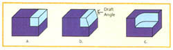
Figure 1: The EMSIM endmilling simulator can provide data on step cuts (a), Step cuts with draft angles (b), or corner cuts (c).
(Click for larger image)Using tool, work-material, and machining-parameter data entered by the user, EMSIM can simulate a step cut, a step cut with a draft angle, or a corner cut (Figure 1). As it runs the simulation, the program calculates the cutting forces, the bending moment and bending stress on the tool, cutter deflections, the surface-form error, the power spectrum of force signal, and the peripheral surface finish. EMSIM is still under development, and new features are being added. Some of these features were not available at the time of this study, but will be used in follow-up research.
For this initial study, the researchers performed one rough and one finish cut. In between these operations, they measured the cut with a Renishaw touch-trigger probe and ran a simulation of the finish cut using the probe's data. For each test cut, they performed the following steps:
Step 1: They rough cut a pocket and then probed 20 points on each of the pocket's four sides, collecting data from a total of 80 probed points per pocket. The contour plots in the z-direction (that is, the surface-form error of the sloping vertical faces of these pockets) also were measured.
Step 2: The researchers finish machined the pocket using data from the rough-cut measurements to adjust the cutting program. After final machining, the probe was again used to measure the dimensions of the pocket and the shape of its vertical walls.
Step 3: Accessing EMSIM through the Internet, the researchers input the data about the rough-cut pockets that were collected in Step 1. The simulator used this data to predict the position (i.e., the pocket dimensions) and the resulting shape of the pocket's vertical walls after finish machining.
The surface-form error measured on each rough-cut pocket's vertical face changed with each trial. Data on this error was entered into EMSIM as an unintentional draft angle (Figure 1b). EMSIM was designed to take draft angles into account so that it could simulate the machining of forged or cast materials, but the ability also proved useful in this multiple-pass investigation. The draft-angle feature allowed the simulation software to make its prediction based upon the past history of the pocket.
However, this draft-angle approach did not allow the researchers to create a perfect representation of the pocket, because it could only show the surface-form error as a straight line. In reality, the endmilling process produces vertical faces with a slight S-shaped curve. To more accurately represent a rough-cut pocket, the EMSIM software is being expanded to include a multiple-pass feature that allows for the surface error generated by a given pass to be precisely added to the depth of cut (DOC) for the next pass.
Step 4: The researchers compared EMSIM's predictions to the measurements of the actual finish-machined pocket. To simplify this analysis, the pocket was milled with a new endmill that did not show any signs of wear. Tool-wear analysis and incorporation into the simulation software will be the subject of future work. Future experiments also will address runout and tool positioning in the spindle.
Calibrating the Equipment
The researchers analyzed the accuracy of their probe and recalibrated the equipment where necessary to ensure the accuracy of the milling operation and the analysis of the results. Because the probe was carried in the spindle of the machine tool, the researchers recalibrated the machine tool's x- and y-axes prior to running their experiments. This was to ensure that when a reading of the table's position was taken after the probe had detected an edge, it would precisely reflect the distance the table had traveled.
These table-position readings were based on the counts of rotary encoders that translated turns of the table's ballscrews into linear measurements. For both the x- and y-axes, the machine tool was originally set up to translate 33,867 encoder counts as a table travel of 1". Using a laser interferometer, the researchers measured the actual table travel, mapping the table errors as a function of the distance traveled. The encoder counts per inch were then adjusted according to the slope of the graph between the table error and the travel distance. Following each adjustment, the test was rerun, allowing for cold- and warm-running of the machine tool. Through this iterative approach, final values for the encoder counts per inch were found.
An initial mapping of the table-travel errors before calibration showed large errors through the length of travel for both the x- and y-axes. With correction, the greatest the x-axis deviated from the target value was no more than about 0.00010" and the y-axis no less than -0.00025". This was accomplished by adjusting the encoder counts to equal 33,865.4 per inch in the x-axis and 33,864.5 per inch for the y-axis.
To further ensure the accuracy of their measurements, the researchers analyzed the probing routine. They began their analysis by installing in the machine tool spindle a probe that had been calibrated by its manufacturer. They then adjusted the position of the probe to reduce runout to less than 0.00005". Following these adjustments, the researchers analyzed three different probing routines to determine which yielded the most accurate measurements. The probe initially operated using a "trigger-on-off" routine. The steps in this probing method are as follows:
 Move the part toward the probe at any feed until contact with the edge of the part triggers the probe.
Stop the table's motion with the probe in triggered position.
Move the part away from the probe at 0.02 in./sec. until the triggering signal ceases.
Signal the computer to take the table's current position.
Move the part away from the probe.
Another probing routine that was evaluated was the "trigger-on-hit" method. With this routine, a slow feed is used to bring the part and probe together. As soon as the probe hits the part's edge, the motion is stopped and a reading is taken. Although the slow feed rate minimizes the threat of overshooting, this method is still the most prone to latency errors.
The third routine evaluated was the "trigger-on-off-constant-feed" method. This routine follows the same steps as the "trigger-on-off" method. The difference is that the same feed that is used to bring the part and probe together is used to back the probe off the part to take the reading.
To evaluate all three probing routines, the researchers measured a hardened-steel 1-2-3 block along the 3" direction. Before probing, the researchers verified that the actual length of the block was 2.9999" using a micrometer accurate to within 0.0001". Bed errors could be ignored during the probing analysis because of the short length of travel.
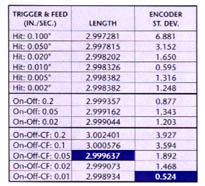
Table 1: The researchers analyzed the accuracy of three different probing routines. Each value was determined with 10 trials per side. The high-lighted measurement in the middle column shows the routine and feed that produced the closest reading. The highlighted measurement in the right-hand column shows the routine and feed that produced the most repeatable readings.
(Click for larger image)The three probing routines were run at many different feed rates. Measurements for each trial were taken on either side of the block at the same point that the researchers had already measured with the micrometer. Table 1 summarizes the findings of this analysis. The trials that, on average, yielded measurements closest to the micrometer reading are highlighted in the middle column on the table. These trials used the trigger-on-off-constant-feed method.
The researchers also converted the measurements for each side of the block into encoder counts. The standard deviation of the measurements, listed in encoder counts in the right-hand column of Table 1, gives an indication of repeatability. The best average is highlighted. Again, the trigger-on-off-constant-feed routine gave the most repeatable results, but at a different feed than the trials that yielded the best length measurement. This value, 0.524 encoder counts, is equivalent to a standard deviation of 15.5µm.
After considering these results, the researchers chose to probe the pockets using the trigger-on-off-constant-feed method at a feed of 0.05 in./sec.
Actual vs. Virtual
With the machine tool and probe calibrated and the probing routine chosen, the researchers were ready to begin milling pockets in the test pieces. Using the same parameters and techniques a shop might use, the researchers milled pockets in 6061 aluminum with a 0.5"-dia., 2-flute, standard-length HSS endmill. The desired dimensions for the pockets were 1.5"X 1.5"X 0.5" deep. Rough-cut pockets were conventionally milled (or up milled), using a "spiraling-out" routine to cut from the center of the pocket feature. Finish cuts were climb milled with varying radial DOCs. Each finish cut started at one corner and milled the four sides in succession.
As the finish cuts progressed, force and acceleration data were taken with a dynamometer and accelerometer. These readings were compared to EMSIM's predictions. Runout was not measured in the present work and was assumed to be 0. (But the force results do indicate some runout was present.) Ongoing investigations will include results for runout.
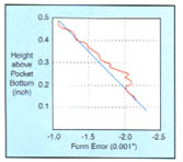
Figure 2: This example of a rough-cut pocket's contour plot shows how an approximate draft angle (blue line) was calculated from the probing data (red line).Figure 2 demonstrates how the draft angle that approximates the surface-form error was computed from a rough-cut contour plot, using the top and bottom points to calculate the slope. The figure is an example of a contour plot representing the surface-form measurements of a rough-cut pocket. The top of the graph (y=0.5) denotes the top of the pocket, and the bottom of the graph (y=0.0) denotes the bottom of the pocket. The x-axis on the graph is the form error, with the desired error being 0.0. The wavy red line is a plot of the actual surface-form-error measurements, while the straight blue line is the draft angle calculated to simulate this error. Although the deepest point the probe could measure was 0.128" above the bottom of the pocket (Figure 3), the data was interpolated to calculate an approximate draft angle for the face from top to bottom.
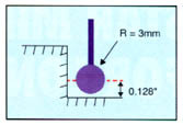
Figure 3: With a 3mm-dia. stylus, the probe was able to measure the pocket's vertical faces to a depth 0.128" above the bottom.
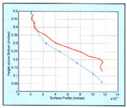
Figure 4: This sample contour plot compares the predicted surface position of the pocket face finish milled with a 0.07" radial DOC (dotted line) to the actual results (solid line).
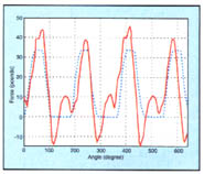
Figure 5: This sample plot compares the predicted force measurements for finish milling the pockets at a 0.05: radial DOC (dotted line) to the actual measurements (solid line).
The simulation was then run with this draft angle and a radial DOC that was modified to compensate for the overcutting of the roughing pass. The surface-form error at the deepest point at which the probe could reach also was incorporated into the finish pass when the pockets were milled. The results of this finish milling for the various DOCs and draft angles are shown in Table 2. The researchers found that conventional rough milling results in overcutting of the rough-cut pockets. This occurs because the forces on the tool pull the cutter into the workpiece when the radial DOC is large. The results of this deflection can be seen in Figure 2, where the sloping vertical face shows a surface-form error range of about 0.001" from the top of the pocket to the bottom.
When the researchers entered the parameters for the simulated finish cut into EMSIM, they allowed for this surface-form error with an adjustment to the radial DOC. This same DOC was used when the pocket was actually finish milled. Climb milling was preferred for the finishing cuts, because the researchers found that overcutting occurred when conventional milling was used for some finish-pass trials at 0.05" and 0.07". A sample contour plot of a climb-milled finish cut is displayed in Figure 4. This plot is for a 0.07" radial DOC. On this plot, the actual results are compared to the predicted EMSIM contour.
Good Agreement Found
Table 2 summarizes all the finish-cut probing. The values for the "Range of Surface-Form Error" column were calculated from the maximum surface errors (at the bottom of the pockets) minus the minimum surface errors (at the top). Figure 5 shows the predicted and the actual forces recorded during the finish-cut pass at 0.05". As indicated in Figure 5, the researchers found very good agreement between the predicted forces and the actual forces generated. Figure 5 does show some disagreement, but much of this can be attributed to runout, which is indicated in the figure by the unequal peaks in the plot of the actual forces.
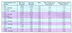
Table 2: This summary of dynamometer readings, EMSIM force predictions, and probing results shows close agreement between predicted and actual measurements.
(Click for larger image)
In general, the shape of the experimental contours agreed well with the shape EMSIM predicted for the finishing cuts (excluding tool wear). The range of the experimental contours also agreed well with the EMSIM theory. In the last column of Table 2 (where experiment and theory are compared on adjacent lines) the agreement is good for all finishing cuts. For instance, EMSIM predicted a surface-form-error range of 0.00112" for a climb-milled finishing cut with a radial DOC of 0.07". The actual range was 0.00113". The range for a 0.005" DOC was predicted to be 0.00025", compared to an actual range of 0.00024".
The maximum surface-form error showed undercutting at the smallest DOCs and good agreement between experiment and theory. At larger DOCs, the agreement between experiment and actual was unreliable. It should be noted that the static version of EMSIM was used here, which does not include feedback. That is, deflections were not fed back to adjust the chipload calculation.
Through the preliminary study, the researchers found that, as expected, a finishing pass could bring the contour of the pocket's vertical face closer to the desired line. However, the shape of the contour will not change significantly unless additional finishing passes are used to trim out the bottom inside corner of the pocket where material still remains from the first finishing pass. The researchers also concluded that more-accurate predictions would be possible if future versions of EMSIM could characterize worn tool behavior. The researchers will be trying to achieve even greater accuracy in future studies. Future plans call for multiple-pass finishing cuts to achieve more verticality in the pocket walls.
About the Authors
This article is adapted from a paper originally published in Volume XXV of the Transactions of the North American Manufacturing Research Institution of the Society of Mechanical Engineers, 1997. When the original paper was written, Matthew Mueller was a graduate student in the Department of Mechanical Engineering, University of California at Berkeley. Richard DeVor is director of the Machine Tool Agile Manufacturing Research Institute at the University of Illinois at Urbana-Champaign, and Paul Wright is a professor of mechanical engineering at the University of California at Berkeley
Related Glossary Terms
- calibration
calibration
Checking measuring instruments and devices against a master set to ensure that, over time, they have remained dimensionally stable and nominally accurate.
- climb milling ( down milling)
climb milling ( down milling)
Rotation of a milling tool in the same direction as the feed at the point of contact. Chips are cut to maximum thickness at the initial engagement of the cutter’s teeth with the workpiece and decrease in thickness at the end of engagement. See conventional milling.
- conventional milling ( up milling)
conventional milling ( up milling)
Cutter rotation is opposite that of the feed at the point of contact. Chips are cut at minimal thickness at the initial engagement of the cutter’s teeth with the workpiece and increase to a maximum thickness at the end of engagement. See climb milling.
- depth of cut
depth of cut
Distance between the bottom of the cut and the uncut surface of the workpiece, measured in a direction at right angles to the machined surface of the workpiece.
- dynamometer
dynamometer
When drilling, a device for measuring the generated torque and axial force (thrust). When milling, a device for measuring the generated torque and feed force. When turning, a device for measuring the tangential, feed and radial forces.
- endmill
endmill
Milling cutter held by its shank that cuts on its periphery and, if so configured, on its free end. Takes a variety of shapes (single- and double-end, roughing, ballnose and cup-end) and sizes (stub, medium, long and extra-long). Also comes with differing numbers of flutes.
- endmilling
endmilling
Operation in which the cutter is mounted on the machine’s spindle rather than on an arbor. Commonly associated with facing operations on a milling machine.
- feed
feed
Rate of change of position of the tool as a whole, relative to the workpiece while cutting.
- finish cut
finish cut
Final cut made on a workpiece to generate final dimensions or specified finish. Often made using reduced feeds and higher speeds. Generally, the better the surface finish required, the longer the finish cut takes. Also, the final cut taken on an electrical-discharge-machined part.
- gang cutting ( milling)
gang cutting ( milling)
Machining with several cutters mounted on a single arbor, generally for simultaneous cutting.
- high-speed steels ( HSS)
high-speed steels ( HSS)
Available in two major types: tungsten high-speed steels (designated by letter T having tungsten as the principal alloying element) and molybdenum high-speed steels (designated by letter M having molybdenum as the principal alloying element). The type T high-speed steels containing cobalt have higher wear resistance and greater red (hot) hardness, withstanding cutting temperature up to 1,100º F (590º C). The type T steels are used to fabricate metalcutting tools (milling cutters, drills, reamers and taps), woodworking tools, various types of punches and dies, ball and roller bearings. The type M steels are used for cutting tools and various types of dies.
- micrometer
micrometer
A precision instrument with a spindle moved by a finely threaded screw that is used for measuring thickness and short lengths.
- milling
milling
Machining operation in which metal or other material is removed by applying power to a rotating cutter. In vertical milling, the cutting tool is mounted vertically on the spindle. In horizontal milling, the cutting tool is mounted horizontally, either directly on the spindle or on an arbor. Horizontal milling is further broken down into conventional milling, where the cutter rotates opposite the direction of feed, or “up” into the workpiece; and climb milling, where the cutter rotates in the direction of feed, or “down” into the workpiece. Milling operations include plane or surface milling, endmilling, facemilling, angle milling, form milling and profiling.
- milling machine ( mill)
milling machine ( mill)
Runs endmills and arbor-mounted milling cutters. Features include a head with a spindle that drives the cutters; a column, knee and table that provide motion in the three Cartesian axes; and a base that supports the components and houses the cutting-fluid pump and reservoir. The work is mounted on the table and fed into the rotating cutter or endmill to accomplish the milling steps; vertical milling machines also feed endmills into the work by means of a spindle-mounted quill. Models range from small manual machines to big bed-type and duplex mills. All take one of three basic forms: vertical, horizontal or convertible horizontal/vertical. Vertical machines may be knee-type (the table is mounted on a knee that can be elevated) or bed-type (the table is securely supported and only moves horizontally). In general, horizontal machines are bigger and more powerful, while vertical machines are lighter but more versatile and easier to set up and operate.